
Ceramic honeycomb filter, its production method, and plugging material for ceramic honeycomb filter

a technology of ceramic honeycomb and honeycomb filter, which is applied in the direction of domestic applications, machines/engines, chemical/physical processes, etc., can solve the problems of reducing engine power, difficult to make the thermal expansion coefficient of cordierite ceramic honeycomb structure equal to that of the plug, and relatively large thermal expansion coefficient. , to achieve the effect of small difference in thermal expansion coefficient, excellent thermal shock resistance, and small residual stress

Active Publication Date: 2007-02-22
HITACHI METALS LTD
View PDF9 Cites 35 Cited by
  • Summary
  • Abstract
  • Description
  • Claims
  • Application Information

AI Technical Summary

Benefits of technology

[0011] Accordingly, an object of the present invention is to provide a ceramic honeycomb filter with small difference in a thermal expansion coefficient between the partition walls of a sintered ceramic honeycomb body and plugs, and with small residual stress because of a low plug-bonding temperature, thereby having excellent thermal shock resistance.
[0014] The inventors have found that by forming a sintered ceramic honeycomb body by a material comprising cordierite as a main component, and by forming plugs by a plugging material containing ceramic particles and colloidal oxide, the colloidal oxide is converted to an amorphous oxide matrix even by low-temperature heating, thereby providing a ceramic honeycomb filter with small difference in a thermal expansion coefficient between the sintered ceramic honeycomb body and the plugs, and with small residual stress because of the low-temperature bonding of the plugs. The present invention has been completed based on this finding.

Problems solved by technology

When the captured particulate matter is excessively accumulated in the ceramic honeycomb filter, there is likely to arise increased pressure loss in the filter, resulting in decrease in the engine power.
It has been found, however, that when the plugging material is heated to a cordierite-forming temperature (for instance, 1300° C.) or higher to bond it to the sintered ceramic honeycomb body as in the above conventional technologies, it is difficult to make the thermal expansion coefficient of the cordierite ceramic honeycomb structure equal to that of the plugs.
However, because the plugging material does not pass through the narrow slit of the extrusion die, cordierite crystals are randomly oriented, resulting in a relatively large thermal expansion coefficient.
Large residual stress is likely to cause cracking in the plugs or in interfaces between the plugs and the honeycomb structure, and the peeling of the plugs, due to thermal shock by an exhaust gas and mechanical shock by engine vibration and vibration by contact with roads when mounted to automobiles.
It has been found, however, that because the cordierite honeycomb structure has a small thermal expansion coefficient while the plugs composed of mullite and alumina cement have a relatively large thermal expansion coefficient, it is likely that cracking occurs between the ceramic honeycomb structure and the plugs by thermal shock by an exhaust gas, and that the plugs peel off, when mounted to an automobile.

Method used


Image

  • Ceramic honeycomb filter, its production method, and plugging material for ceramic honeycomb filter
  • Ceramic honeycomb filter, its production method, and plugging material for ceramic honeycomb filter
  • Ceramic honeycomb filter, its production method, and plugging material for ceramic honeycomb filter

Examples


Embodiment Construction

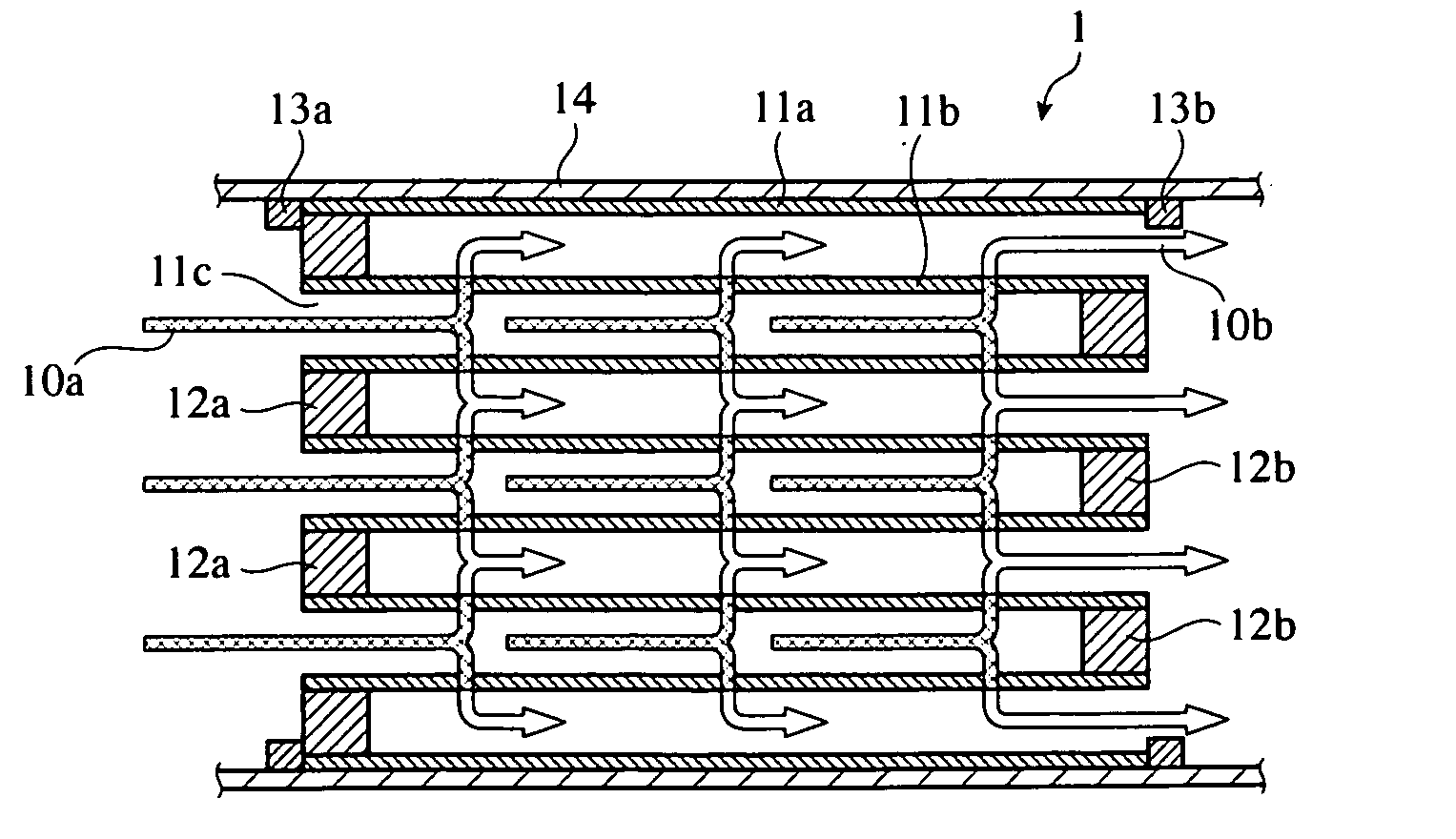
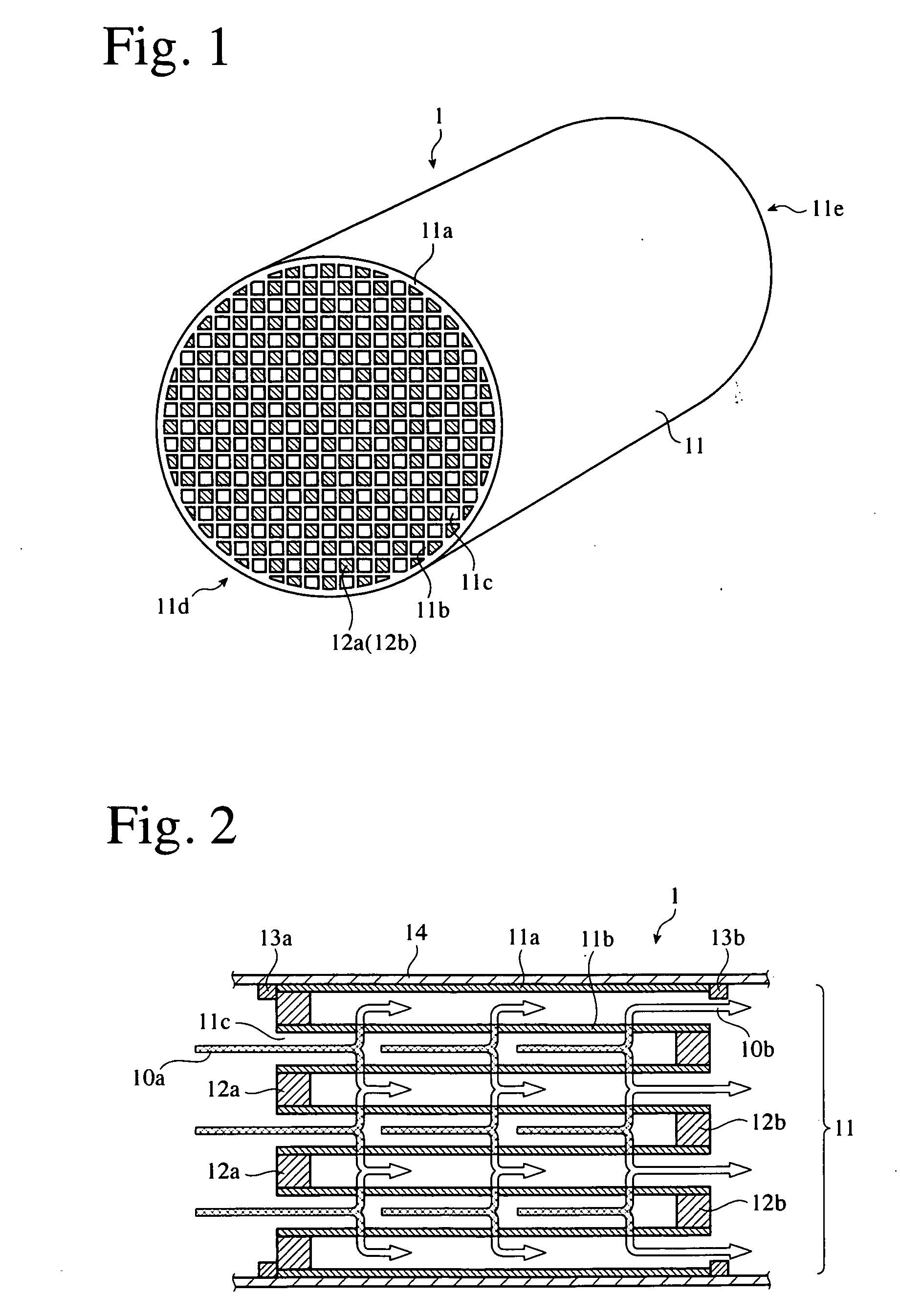
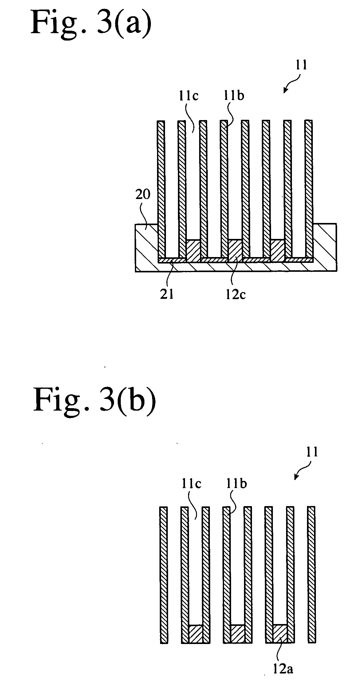
[0025] The ceramic honeycomb filter of the present invention comprises a sintered ceramic honeycomb body made of a cordierite-based ceramic material, and plugs formed in predetermined flow paths of the sintered ceramic honeycomb body, at least part of the plugs being formed by a plugging material comprising ceramic particles and colloidal oxide. By filling the plugging material into the predetermined flow paths of the sintered ceramic honeycomb body and then heating it, the colloidal oxide is converted to an amorphous oxide matrix, resulting in strong bonding of the plugs to the sintered ceramic honeycomb body. The plugging material for plugs will be explained first, and the ceramic honeycomb filter and its production method will then be explained.

[0026] [1] Plugging Material

[0027] Ceramic particles in the plugging material for the ceramic honeycomb filter of the present invention are preferably cordierite particles and / or amorphous silica particles. This is because small thermal ...


PUM

PropertyMeasurementUnit
Temperatureaaaaaaaaaa

Abstract

A ceramic honeycomb filter comprising a sintered ceramic honeycomb body having porous partition walls defining flow paths, and plugs formed in predetermined flow paths for removing particulate matter from an exhaust gas passing through the porous partition walls, the sintered ceramic honeycomb body being formed by a cordierite-based ceramic material, at least part of the plugs comprising ceramic particles and an amorphous oxide matrix formed from colloidal oxide.

Description

FIELD OF THE INVENTION [0001] The present invention relates to a ceramic honeycomb filter for removing particulate matter from an exhaust gas discharged from diesel engines, its production method, and a plugging material for producing such ceramic honeycomb filter. BACKGROUND OF THE INVENTION [0002] To remove particulate matter from an exhaust gas from diesel engines, a particulate-matter-capturing ceramic honeycomb filter comprising a sintered ceramic honeycomb body with porous partition walls, through which the exhaust gas containing particulate matter passes, namely, a diesel particulate filter (DPF) has been developed and put into practical use. The ceramic honeycomb filter comprises a sintered ceramic honeycomb body having porous partition walls defining flow paths and a peripheral wall, and plugs alternately sealing both ends of the flow paths. Because the ceramic honeycomb filter is exposed to high temperatures, the sintered ceramic honeycomb body is made of heat-resistant co...

Claims


Application Information

Patent Timeline
IPC IPC(8): B01D39/06B01D39/20B01D46/24B28B11/00F01N3/02F01N3/022
CPCB01D46/2418B01D46/2455B28B11/006F01N3/0222F01N2330/06Y10T428/24149Y10S55/05Y10S264/48Y10S55/30Y10S55/10Y02T10/20Y02T10/12B01D39/20B01D46/00
Inventor TOKUMARU, SHINYA
Owner HITACHI METALS LTD
Learn More