Fuel saving heater for internal combustion engine

a technology for internal combustion engines and heaters, which is applied in the direction of machines/engines, combustion air/fuel air treatment, and feed systems, etc. it can solve the problems of increasing the risk of fire or explosion, reducing the efficiency of fuel consumption, and reducing the risk of fuel overheating, so as to improve the quality of fuel and improve the temperature stability. , the effect of preventing the fuel from overheating

Inactive Publication Date: 2007-03-01
WAY LAN +1
View PDF7 Cites 7 Cited by
  • Summary
  • Abstract
  • Description
  • Claims
  • Application Information

AI Technical Summary

Benefits of technology

[0012] This invention relates to a fuel heating device in which a housing means defines an inlet end, inner chamber, and outlet end to allow the fuel from a fuel tank in an automobile to be heated and then be delivered to an internal combustion engine for efficient burning. In the center portion of the inner chamber, there is an infrared annular member that further defines an interior passageway for some fuel passing through from the inlet end to be heated within. The annular member, made of heat retaining materials, is elongated in shape with its most part in small dimension at size near the inlet end and the remaining part in large dimension at size near the outlet end. On the outside surface of the annular member, there is sintered with a multi-metallic layer. The layer can enhance the temperature stability in the inner chamber by gradually releasing the heat of the annular member slowly. Wrapping around the outside surface of the annular member with small size, there is a spirally electrical heating pipe that is made of heat conductive materials. Besides the aforementioned annular member and heating pipe, there are still multi-elements plates and filling metal gauzes within the inner chamber. The multi-elements plates may be disposed near the inlet end or the outlet end within the inner chamber. Both of the pla

Problems solved by technology

Furthermore, both media may sometimes inevitably overheat the fuels to some extent so that the automobile is to be exposed to a great danger of fire or explosion should fuel leakages out of the fuel pipe of the automobile occur in an accident.
Although many heating devices of the prior arts have proved to be operationally efficient in fuel saving for engines of automobiles,

Method used


Image

  • Fuel saving heater for internal combustion engine
  • Fuel saving heater for internal combustion engine
  • Fuel saving heater for internal combustion engine

Examples


Embodiment Construction

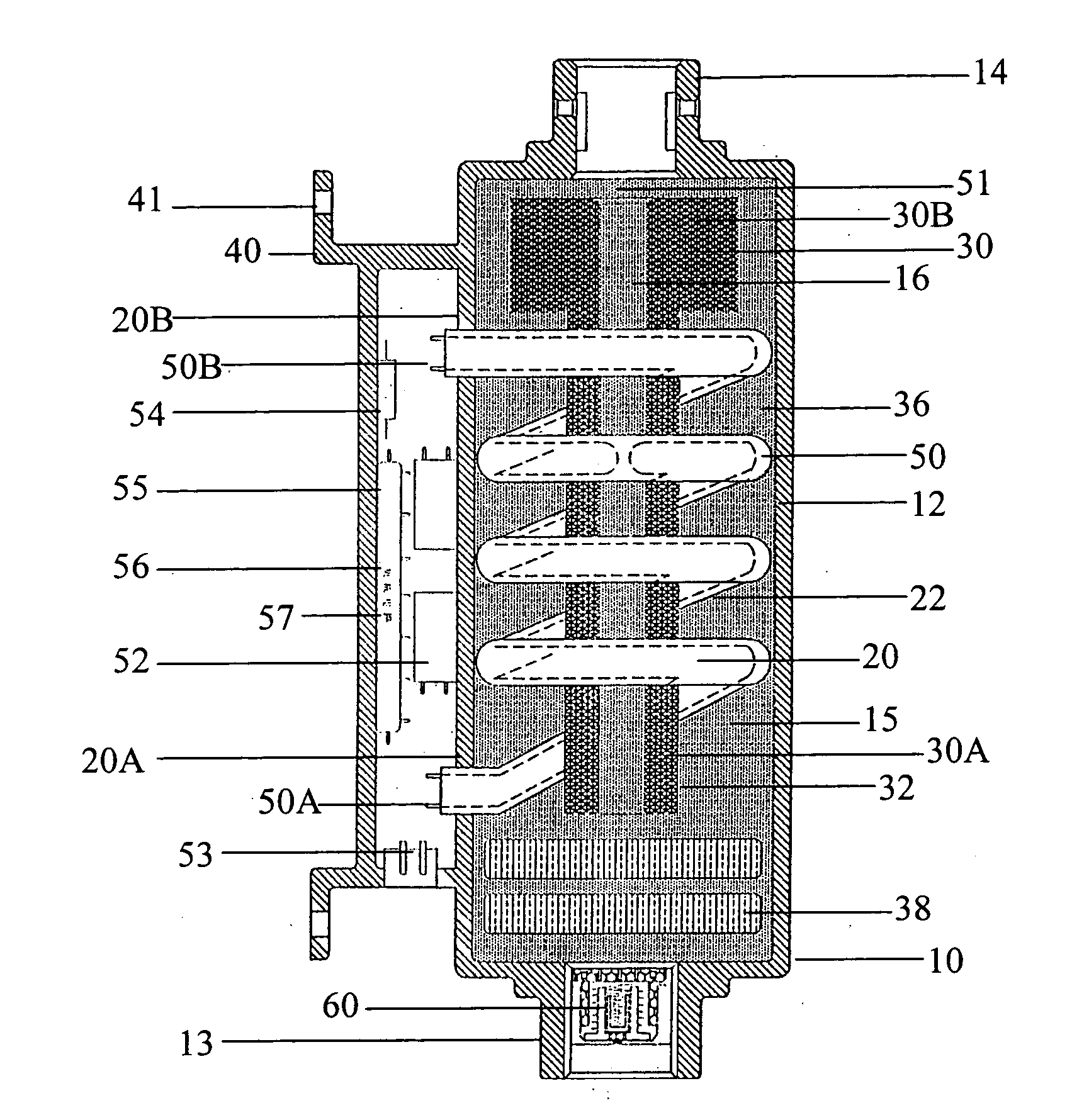
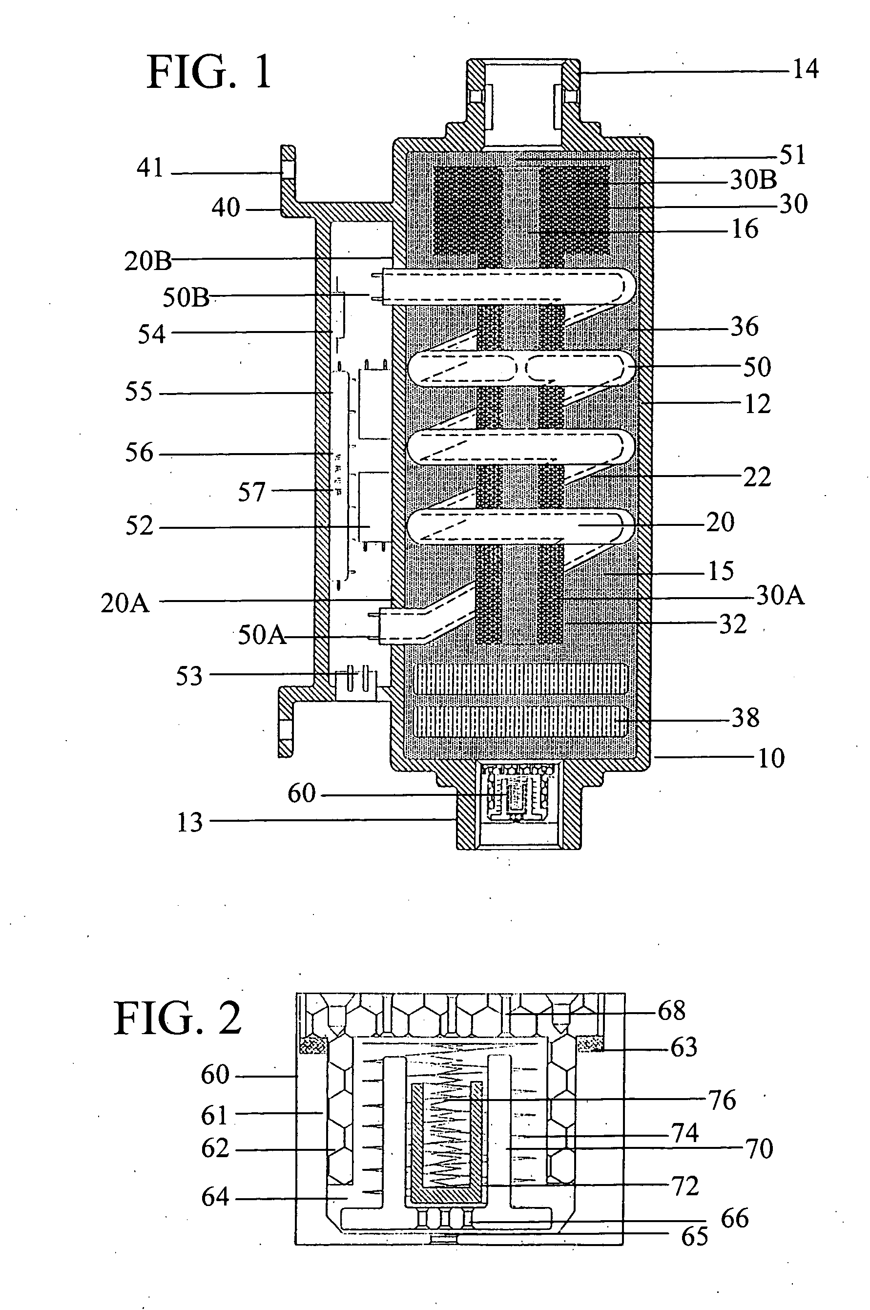
[0017] With particular reference to FIG. 1, a fuel saving device 10 in accordance with the preferred embodiment of the present invention comprises of an elongated housing means 12 with an inlet end 13 at its one side and an outlet end 14 at its other side, and a holding base 40 beneath it to be installed on any convenient position in an automobile preferably as close to an internal combustion engine (not shown) as possible. The housing means 12 further defines an inner chamber 15 along with the inlet end 13 and the outlet end 14 for establishing a flow of the fuel from a fuel tank (not shown) to the engine with the device 10 in between. There is an infrared annular member 30 disposed in the center portion of the inner chamber 15 between the inlet end 13 and the outlet end 14. The annular member 30 elongated in shape can be divided into two different parts. The large part is in small dimension at size 30A with its one side situated near the inlet end 13. The small part is in large di...


PUM


Abstract

A fuel saving device powered by electrical energy from a battery in an automobile has many competitive advantages over its predecessors such as efficient operation, inexpensive price, compact size, safe use, easy installation, simple replacement, etc. The device may be disposed at any convenient position preferably as close to the engine as possible. The device is operative automatically without any necessary alteration or modification to the original design of the automobile. The device has a housing means that further defines an inner chamber, inlet end, and outlet end. An infrared annular member made of heat retaining materials is disposed in the center portion of the inner chamber. A spirally electrical heating pipe, made of heat conductive materials, wraps firmly around the outside surface of the annular member. Within the heating pipe, there are not only stuffing gauzes with thermally conductive, electrically insulating nature, but also at least two sets of electrical heating elements. The heating elements are to generate sufficient heat to elevate the temperature for the heating pipe, the annular member, and filling metal gauzes stuffed within the inner chamber. All of aforesaid three heat exchangers are then to elevate the temperature of the fuel via thermal conduction by means of direct contact. Multi-elements plates within the inner chamber are to restore the fuel back to the original stage at refinery level without bad influences of fuel additives. An electrical system including a temperature sensor to detect the fuel temperature is to precisely control the flow of the electrical current from the battery to the heating elements. A fuel stabilizer is also provided to constantly balance the amount and the pressure of the fuel in order to prevent unnecessary fuel waste for the engine.

Description

BACKGROUND OF THE INVENTION [0001] 1. Field of the Invention [0002] The invention generally relates to an internal combustion engine in an automobile, and specifically to an electrical fuel saving device for heating, catalyzing, and stabilizing the fuel flowing from a fuel tank in the automobile in order to maintain fuel temperature within a predetermined range, improve fuel quality, and prevent excessive fuel pressure to be delivered to the engine for efficient combustion. [0003] 2. Description of Prior Art [0004] It is a well-known fact in automobile industry that hydrocarbon fuels such as gasoline and diesel are more efficiently burned for an internal combustion engine if their temperatures can be elevated and maintained within an optimum range than ambient temperatures at various weather conditions prior to intended combustion. To improve the fuel efficiency significantly, many engineers in prior arts have designed numerous devices trying to elevate the temperatures of the fuels...

Claims


Application Information

Patent Timeline
IPC IPC(8): F02G5/00F02M27/00
CPCF02M27/02F02M27/06
Inventor DONG, NAIQIANG
Owner WAY LAN
Why Eureka
Try Eureka