
Cables with stranded wire strength members

a technology of stranded wires and strength members, which is applied in the direction of insulated conductors, power cables, cables, etc., can solve the problems of armor wire corrosion and torque imbalance, difficulty in removing oil or gas trapped therein, wireline cable damage, etc., to prevent or minimize dangerous gas migration, improve corrosion resistance, and improve the effect of corrosion resistan

Active Publication Date: 2007-03-01
SCHLUMBERGER TECH CORP
View PDF19 Cites 69 Cited by
  • Summary
  • Abstract
  • Description
  • Claims
  • Application Information

AI Technical Summary

Benefits of technology

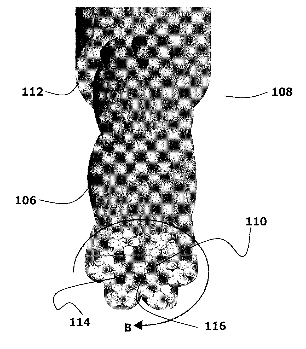
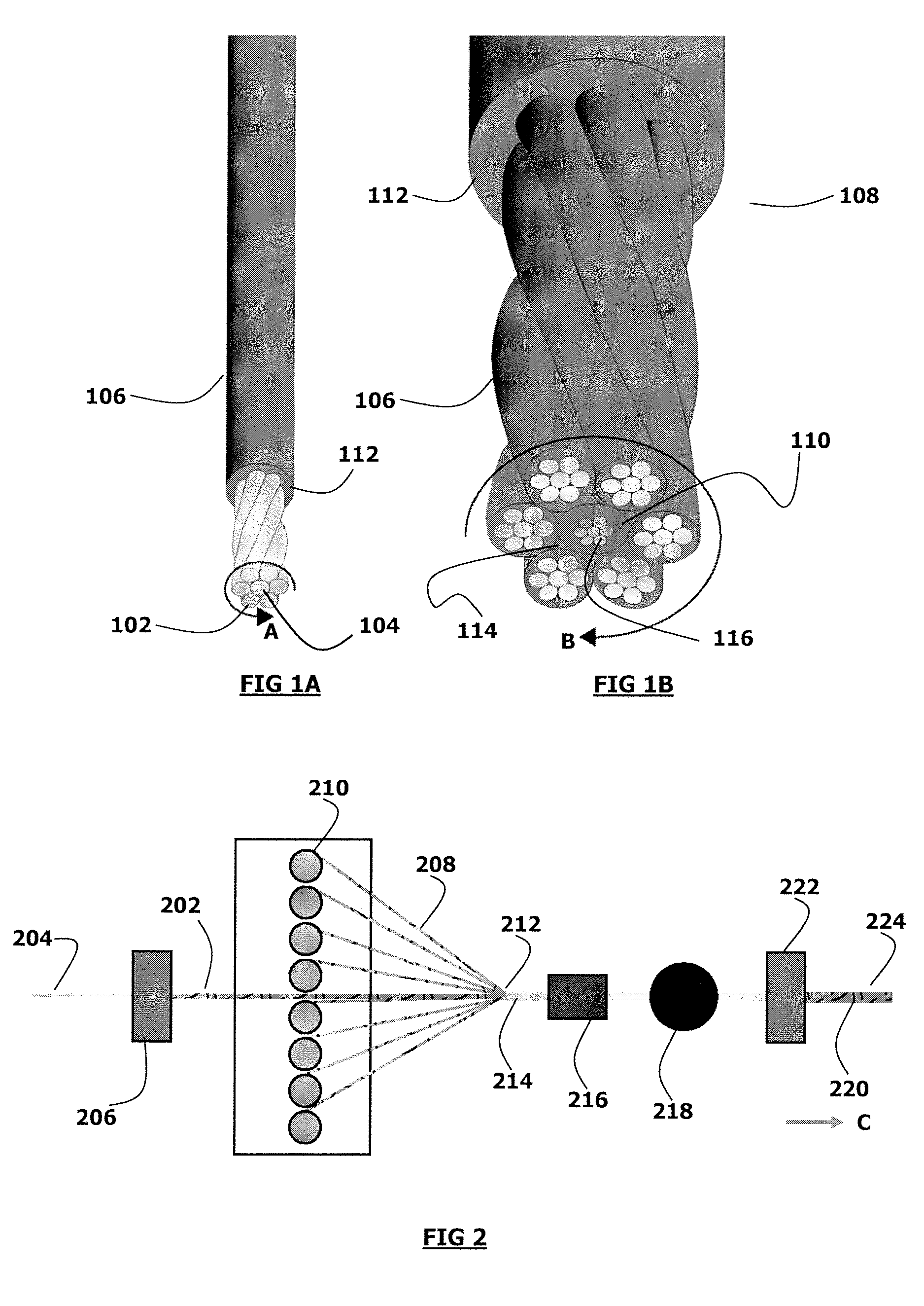
[0010] The invention relates to wellbore cables, and in particular, the invention relates to high strength cables formed of strength members. The cables are used with devices to analyze geologic formations adjacent a wellbore. Cables of the invention may be of any practical design, including monocables, coaxial cables, quadcables, heptacables, slickline cables, multi-line cables, etc. Cables described herein have improved corrosion resistance, torque balancing, and may also help to prevent or minimize dangerous gas migration from a wellbore to the surface.

Problems solved by technology

Formations generally comprising shale, which may also encapsulate oil-bearing formations, may have porosities much greater than that of sandstone or limestone, but, because the grain size of shale is very small, it may be very difficult to remove the oil or gas trapped therein.
Two common causes of wireline cable damage are armor wire corrosion and torque imbalance.
Corrosion commonly leads to weakened or broken armor wires.
While zinc protects the steel at moderate temperatures, studies have shown that passivation of zinc in water (that is, loss of its corrosion-protection properties) can occur at elevated temperatures.
Once the armor wire begins to rust, it loses strength and ductility quickly.
Although the cable core may still be functional, it is not economically feasible to replace the armor wire, and the entire cable must be discarded.
Once corrosive fluids infiltrate into the annular gaps, it is difficult or impossible to completely remove them.
Even after the cable is cleaned, the corrosive fluids remain in the annular spaces damaging the cable.
Neither of these options is very practical with wireline cable.
The second approach may lead to decreased cable life due to abrasion issues.
This compresses the cable core and can cause insulation creep on conductors, leading to possible short circuits or broken conductors.
Also, when inner and outer wire armor layers, each having wires orientated in helix configurations, are used, this leads to torque development when the cable is placed under an axial load.
Another problem encountered with traditional armored wire cables occurs in high-pressure wells, the wireline is run through one or several lengths of piping packed with grease to seal the gas pressure in the well while allowing the wireline to travel in and out of the well.
As the wireline goes over the upper sheave at the top of the piping, the armor wires tend to spread apart slightly and the pressurized gas is released, where it becomes an explosion hazard.

Method used


Image

  • Cables with stranded wire strength members
  • Cables with stranded wire strength members
  • Cables with stranded wire strength members

Examples


Embodiment Construction

[0030] Illustrative embodiments of the invention are described below. In the interest of clarity, not all features of an actual implementation are described in this specification. It will of course be appreciated that in the development of any such actual embodiment, numerous implementation-specific decisions must be made to achieve the developer's specific goals, such as compliance with system related and business related constraints, which will vary from one implementation to another. Moreover, it will be appreciated that such a development effort might be complex and time consuming but would nevertheless be a routine undertaking for those of ordinary skill in the art having the benefit of this disclosure.

[0031] The invention relates to high strength cables including stranded wires as strength members, where the cables are dispatched into wellbores used with devices to analyze geologic formations adjacent a well. Methods of manufacturing such cables, and uses of the cables in sei...


PUM

PropertyMeasurementUnit
Fractionaaaaaaaaaa
Fractionaaaaaaaaaa
Fractionaaaaaaaaaa

Abstract

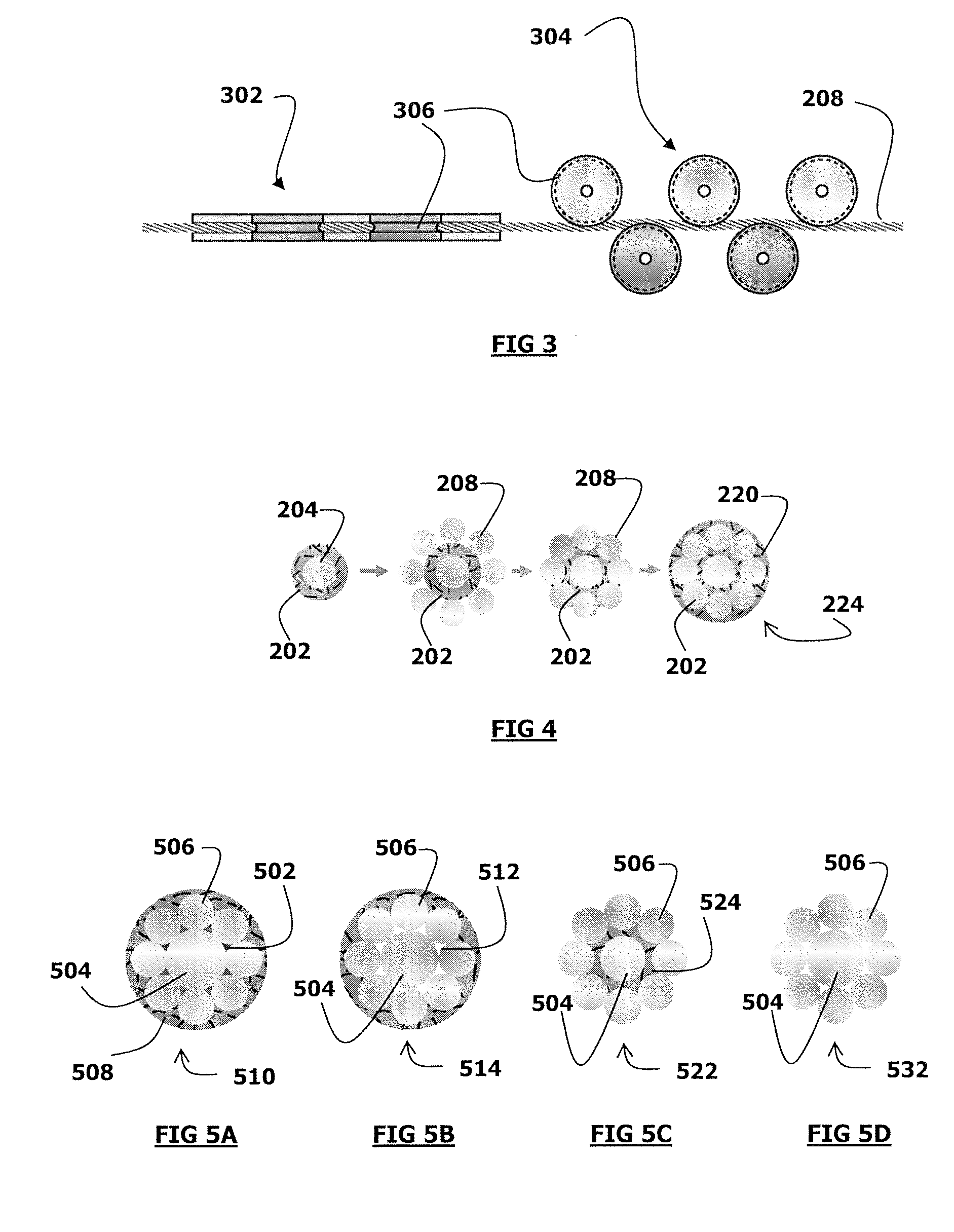
High strength cables formed from strength members. The strength members are formed from bimetallic filament wires which may be encased within a jacket of polymeric material. The bimetallic filament wires wherein the filaments include a high strength core and a corrosion resistant alloy clad forming the outer layer of the filament. The strength members may be used individually, as a central strength member, or even layered around a central axially positioned component or strength member, to form a layer of strength members. Cables of the invention may be of any practical design, including monocables, coaxial cables, quadcables, heptacables, slickline cables, multi-line cables, suspension cables, and the like.

Description

RELATED APPLICATION DATA [0001] This application is a Continuation-In-Part of and also claims the benefit of U.S. patent application Ser. No. 11 / 279,518, filed Apr. 12, 2006, a non-provisional application based upon provisional application Ser. No. 60 / 695,616, filed Jun. 30, 2005, and claims the benefit of the filing date thereof.BACKGROUND OF THE INVENTION [0002] This invention relates to armored wellbore logging cables. In some aspects, the invention relates to high strength cables based upon corrosion resistant stranded wire strength members used with devices to analyze geologic formations adjacent a wellbore, or to perform mechanical services in wellbores. [0003] Generally, geologic formations within the earth that contain oil and / or petroleum gas have properties that may be linked with the ability of the formations to contain such products. For example, formations that contain oil or petroleum gas have higher electrical resistivity than those that contain water. Formations gene...

Claims


Application Information

Patent Timeline
IPC IPC(8): H01B7/18
CPCH01B7/046H01B13/02D07B2207/4059H01B7/2806D07B2401/2025D07B1/162D07B1/068D07B1/147D07B1/16D07B7/145D07B2201/2011D07B2201/2044D07B2201/2046D07B2201/2065D07B2801/12D07B2801/60G02B6/4416G02B6/441
Inventor VARKEY, JOSEPH
Owner SCHLUMBERGER TECH CORP
Learn More