Bipolar power supply with lossless snubber

a power supply and lossless technology, applied in the direction of electric variable regulation, process and machine control, instruments, etc., can solve the problems of lossless snubbers having some power loss, diodes to suffer reverse breakdown, and lossless snubbers are often impractical, etc., to achieve low output capacitance, wide output voltage range, and high output voltage capability

Inactive Publication Date: 2007-03-01
ADVANCED ENERGY IND INC
View PDF7 Cites 30 Cited by
  • Summary
  • Abstract
  • Description
  • Claims
  • Application Information

AI Technical Summary

Benefits of technology

[0014] The invention provides a power converter suitable for high power and high voltage applications. In one aspect of the invention, a power supply comprises a power converter having rectifiers snubbed with one or more lossless snubber ci

Problems solved by technology

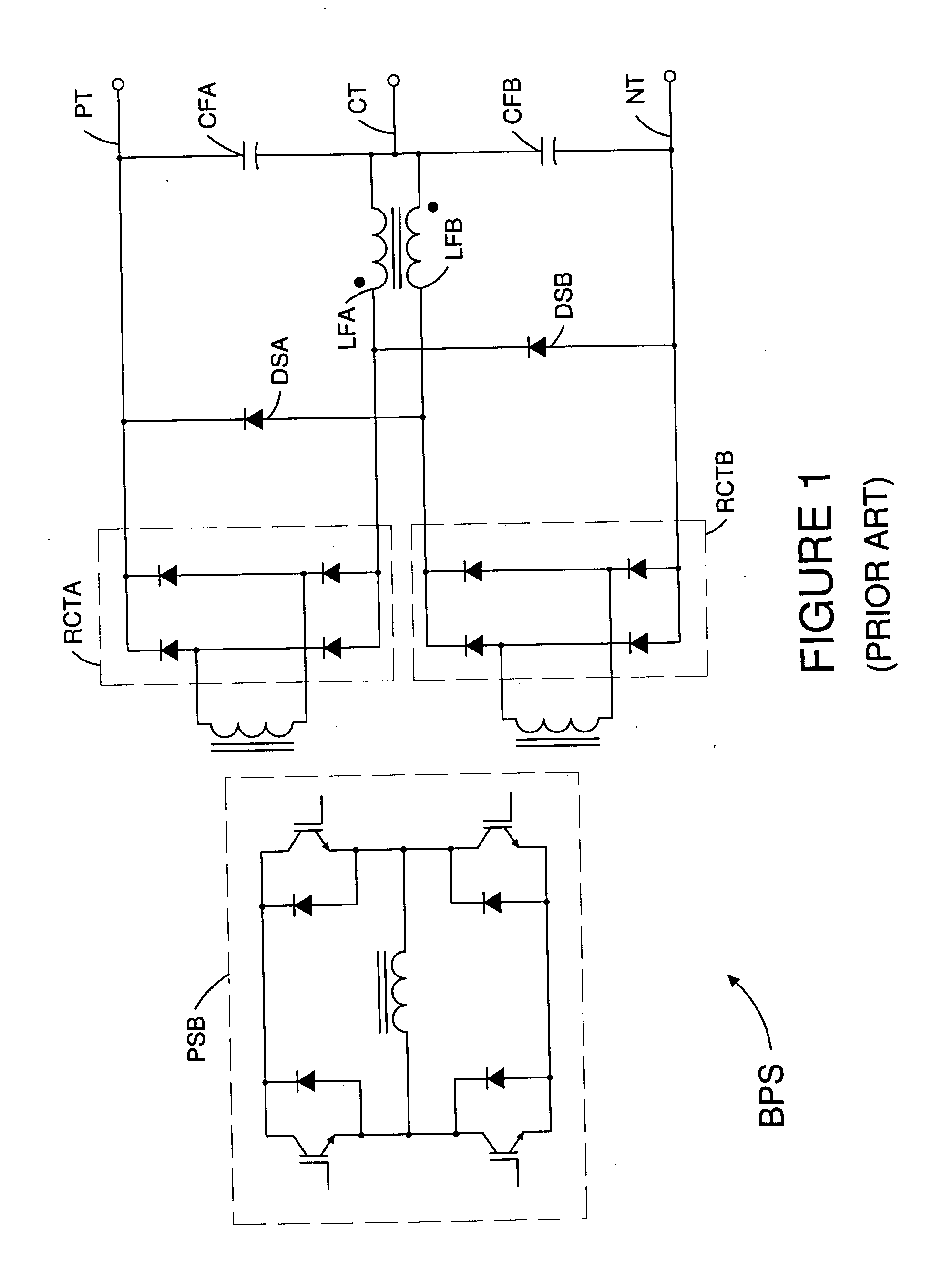
A common problem with isolated dc power converters in which the output of transformer windings is rectified and filtered with an inductor is that the rectifiers require some type of snubbing circuit to prevent energy that is built up in various circuit inductances during the reverse recovery of the rectifier diodes from causing the diodes to suffer reverse breakdown from voltage overshoots that occur in the transformer windings when the rectifier diodes turn off and the stored inductive energy is released.
Dissipative snubbers are often impractical in high power converters, and so a variety of lossless snubber circuits have been developed.
In practice, however, so-called lossless snubbers do have some power losses, but they are much lower that the power losses of dissipative snubbers.
Although this snubbing scheme is simple and effective, it has the disadvantage of limiting the allowable operating range of the inverter duty cycle to values somewhat greater than 0.5 in order to prevent the snubber diodes DSA and DSB from delivering large current pulses to the output filter capacitors CFA and CFB.
This effect limits the available range of voltage conversion ratios obtainable with this power converter circuit.
A further

Method used


Image

  • Bipolar power supply with lossless snubber
  • Bipolar power supply with lossless snubber
  • Bipolar power supply with lossless snubber

Examples


Embodiment Construction

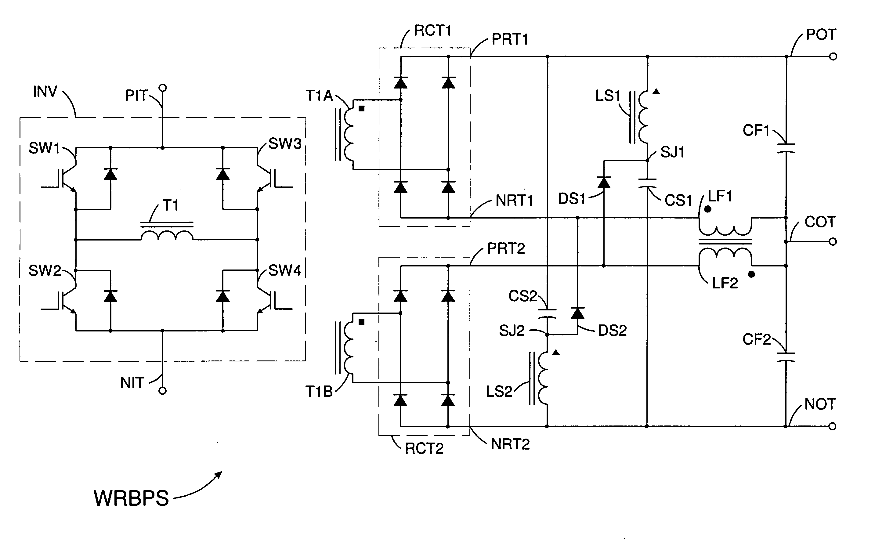
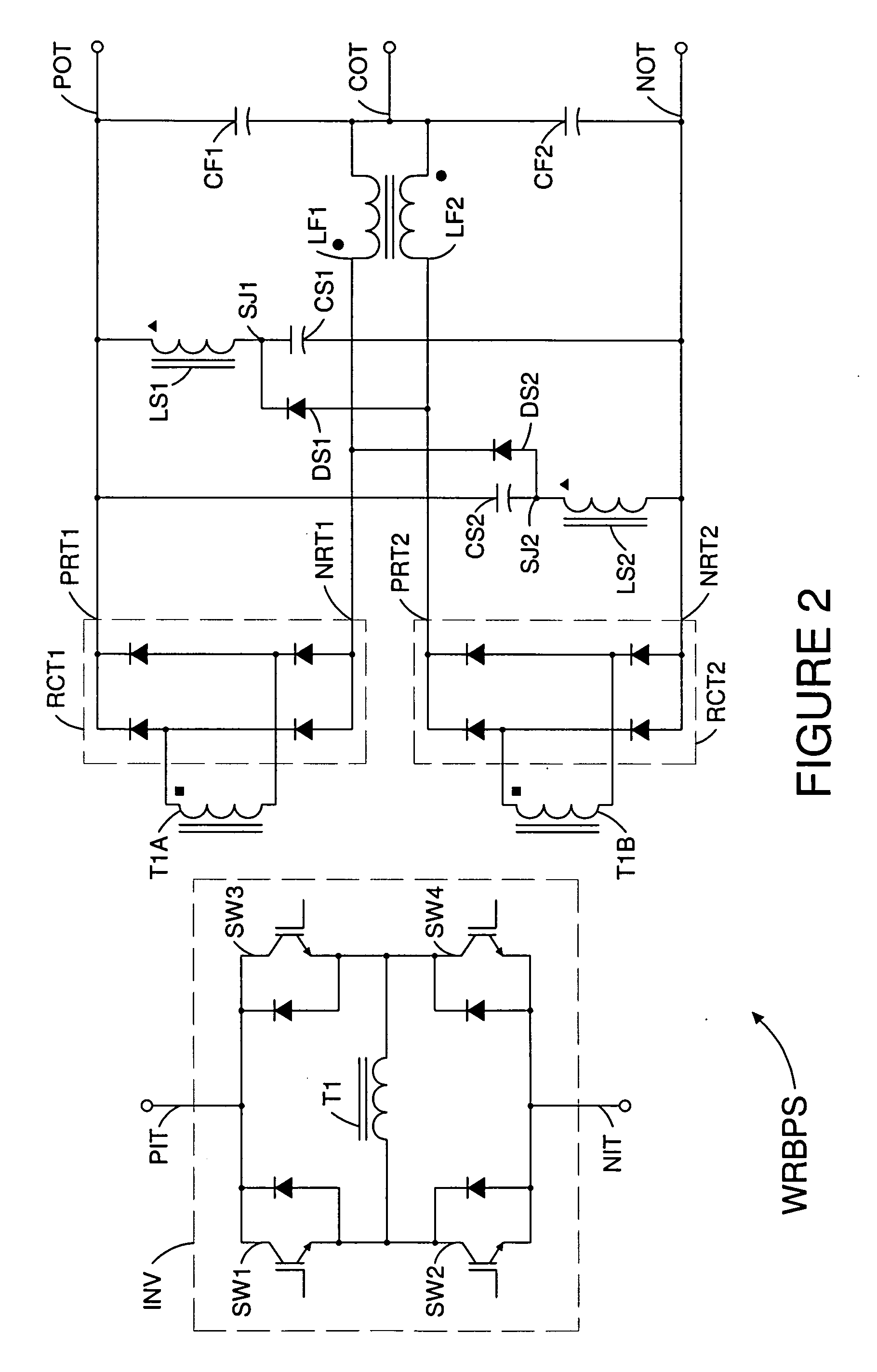
[0023]FIG. 2 illustrates a wide range bipolar power supply in accordance with one embodiment of the invention. Bipolar power supply WRBPS has an inverter INV that receives dc power from input terminals PIT and NIT. The inverter has switches SWI-SW4 that drive a transformer T1. The switches may be operated by a control circuit (not shown) so that the inverter functions as a phase shifted bridge or as a pulse width modulated H bridge. Inverter INV may also be implemented with any known inverter circuit that delivers current pulses into a transformer. Transformer T1 has secondary windings T1A and T1B that supply ac power to bridge rectifiers RCT1 and RCT2. Alternatively, T1 could be replaced with two transformers that serve the same function as T1. Rectifier RCT1 delivers dc power between a positive output terminal PRT1 and a negative output terminal NRT1. Rectifier RCT2 delivers dc power between a positive output terminal PRT2 and a negative output terminal NRT2. Rectifiers RCT1 and R...


PUM


Abstract

In one aspect of the invention, an isolated power converter suitable for high power and high voltage applications comprises stacked rectifiers and lossless snubber circuits with inductors that prevent snubber diodes from delivering large current pulses into output filter capacitors when the duty cycle of the inverter is low, thereby allowing effective snubbing without unduly restricting the voltage conversion range of the power supply. In another aspect of the invention, control circuitry of a power supply comprises both a high bandwidth input current regulator and a low bandwidth output voltage regulator. The combination of a wide bandwidth input current regulator and a low bandwidth output voltage regulator allows the power supply to emulate an inductively loaded uncontrolled rectifier while restricting negative input impedance characteristics to frequencies that are substantially lower than the frequency of the ac power system.

Description

BACKGROUND OF THE INVENTION [0001] 1. Field of the Invention [0002] This invention relates generally to switch mode power converters, and more particularly, to dc power converters suitable for high power and high voltage applications such as plasma processing. [0003] 1. Brief Description of the Prior Art [0004] A common problem with isolated dc power converters in which the output of transformer windings is rectified and filtered with an inductor is that the rectifiers require some type of snubbing circuit to prevent energy that is built up in various circuit inductances during the reverse recovery of the rectifier diodes from causing the diodes to suffer reverse breakdown from voltage overshoots that occur in the transformer windings when the rectifier diodes turn off and the stored inductive energy is released. This problem is often handled by directing the stored energy away from the rectifiers with a snubber circuit. Snubbers that are connected to transformer isolated output cir...

Claims


Application Information

Patent Timeline
IPC IPC(8): H02M3/24
CPCH02M3/335
Inventor HESTERMAN, BRYCE L.ILIC, MILANMALININ, ANDREV B.
Owner ADVANCED ENERGY IND INC
Why Eureka
Try Eureka