Pulse width modulated power inverter output control

Active Publication Date: 2007-03-01
CONSARC
View PDF15 Cites 23 Cited by
  • Summary
  • Abstract
  • Description
  • Claims
  • Application Information

AI Technical Summary

Benefits of technology

[0012] In one aspect, the present invention is a method of controlling the output of a pulse width modulated inverter used, for example, as a power supply for an electro-slag remelting furnace. The inverter is formed from an H-bridge circuit that has at least one switching element in anti-parallel with a diode in each leg of the H-bridge circuit. A substantially resistive, single phase load is connected between the legs of the H-bridge. A first pair of switching elements in the first and second legs of the H-bridge alternatively conduct for the positive half cycle of the output, and a second pair of switching elements in the third and fourth legs of the H-bridge alternatively conduct for the negative half cycle of the output to establish a flow of ac current through the load. One of the first pair of switching elements is pulsed off and on for at least one first pulse period of the positive half cycle while the other one of the first pair of switching elements is conducting, but, then the second switching element of the first pair is pulsed off and on for at least one second pulse period of

Problems solved by technology

Traditional methods of controlling the power to an electro-slag remelting furnace includes transformer tap changing, but, this method requires frequent maintenance and does not typically achieve the required precision.
The more common method of regulating the current is by phase angle control, but, this method tends to generate high levels of harmonics to the supply.
The combination of a single phase load with high harmonics in the approximate range of 800 kilo-watts through 6,000 kilo-watts tends to be problematic for modem three phase electrical supply grids.
If appropriate measures were not taken this would generate dangerously high voltages, which could destroy the switching devices.
The problem is that when switching between a positive

Method used


Image

  • Pulse width modulated power inverter output control
  • Pulse width modulated power inverter output control
  • Pulse width modulated power inverter output control

Examples


Embodiment Construction

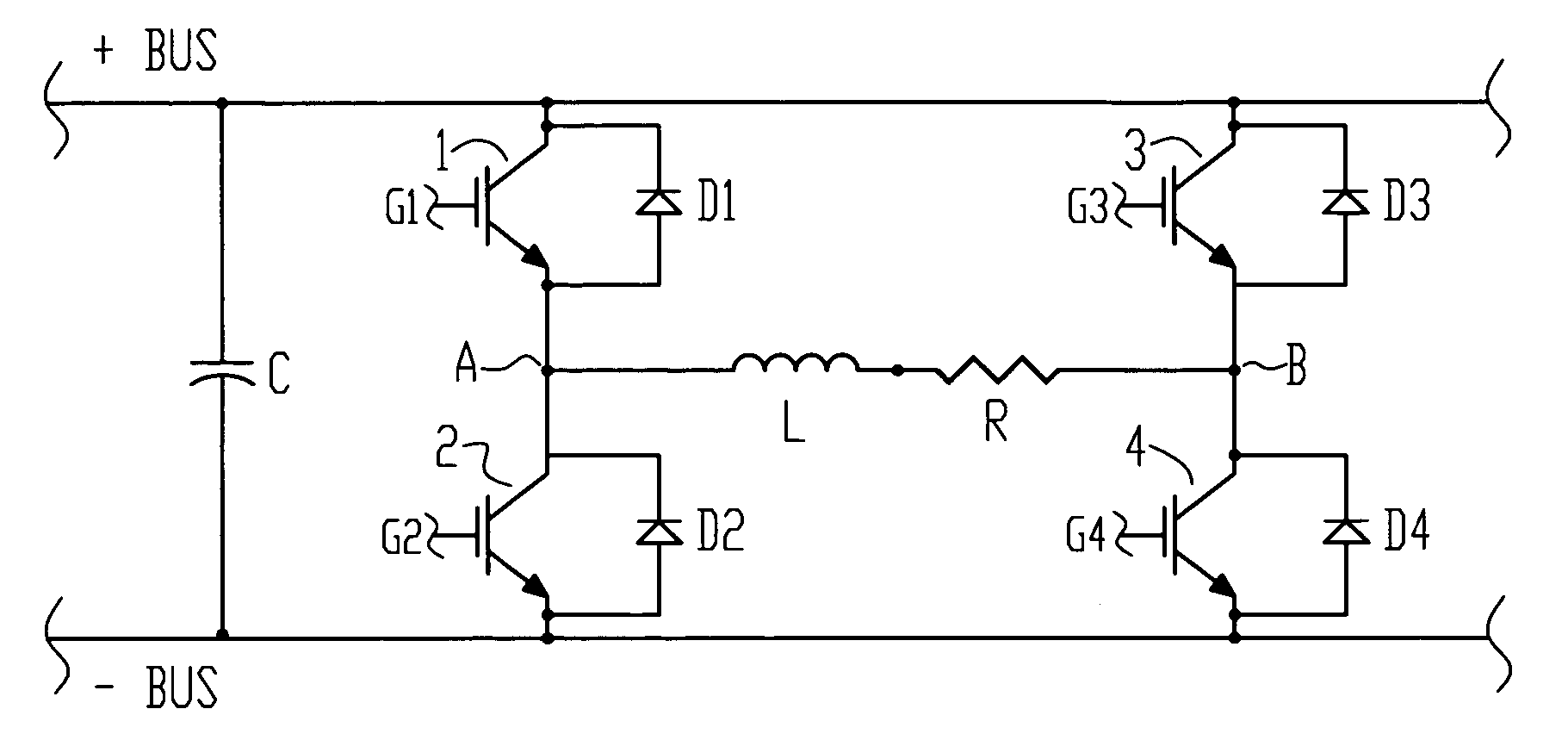
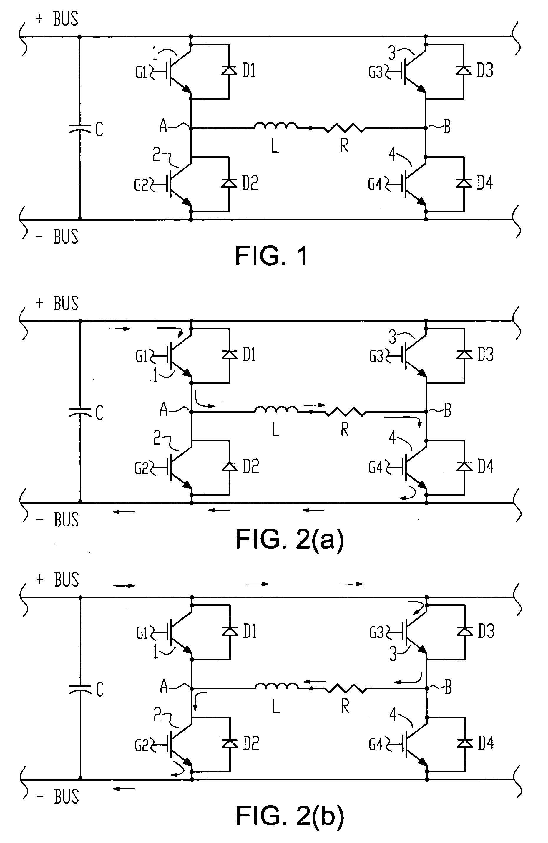
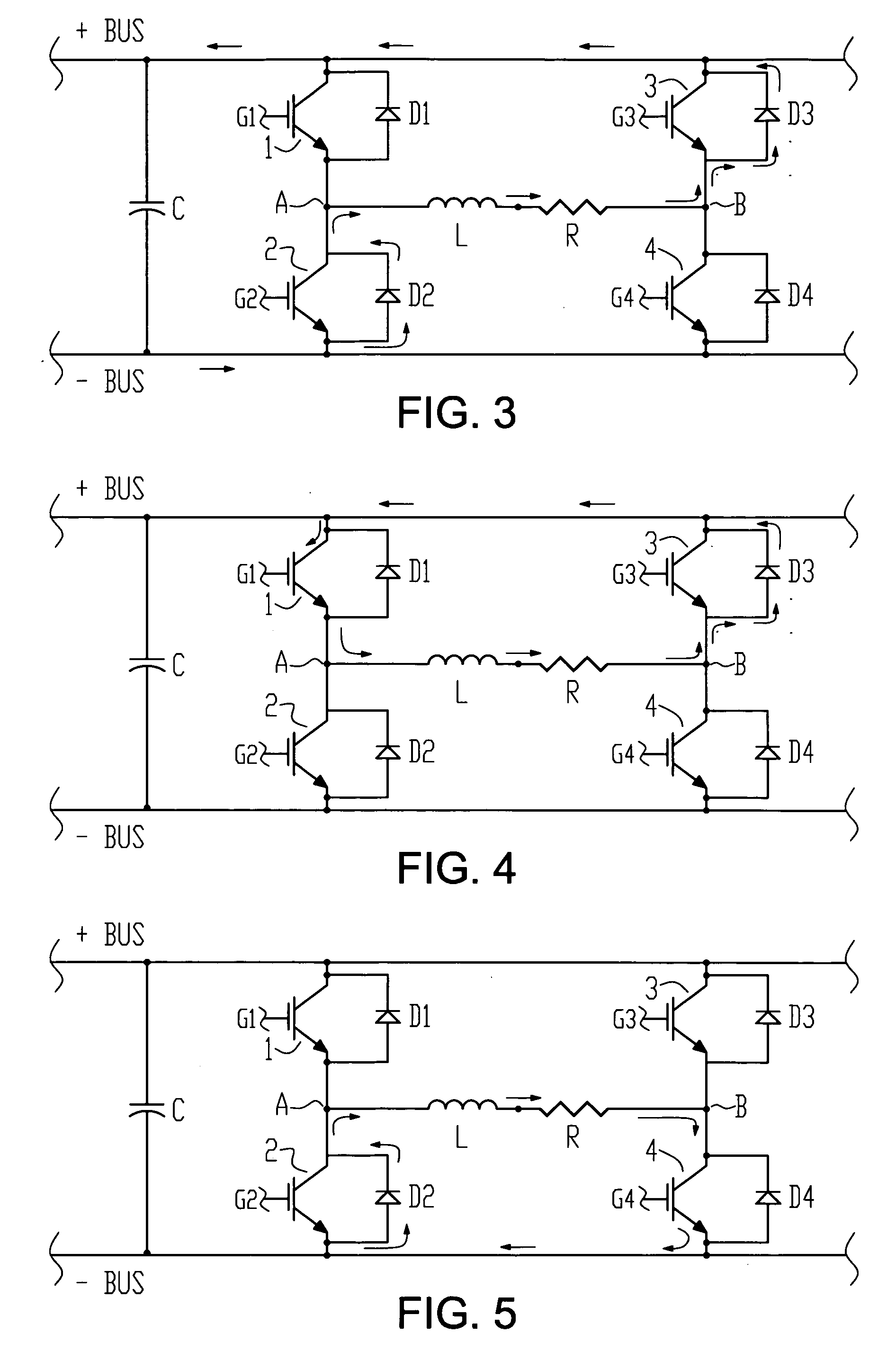
[0022]FIG. 6 illustrates one application in which the PWM inverter output control method of the present invention can be used. DC power is inputted to inverter 6 from a single phase rectifier formed from diodes D5, D6, D7 and D8, with capacitor C serving as an energy storage and filter element. PWM control circuit 8 includes gate driver circuitry for gates G1, G2, G3 and G4 of switching devices 1, 2, 3 and 4, respectively. Although IGBT switching devices are illustrated in FIG. 6, other types of switching devices may be used. Each of the switching devices has an allowed switching rate, as defined by the specification for a specific switching device. The gate driver circuitry controls turn on and turn off of the switching devices, including alternative pulsing of the switching devices as further described below. In some examples of the invention, suitable circuitry provides inputs to the PWM control circuit 8 for regulating the alternative pulsing scheme, including pulse frequency an...


PUM


Abstract

A method is provided for output control of a pulse width modulated power inverter used with a substantially resistive, single phase, ac load such as an electro-slag remelting furnace. In one application of the method, during each of the inverter's half cycle outputs, active switching devices are alternatively pulsed on and off during the half cycle so that only half of the switching transients in the half cycle are handled by one of the active switching devices.

Description

CROSS REFERENCE TO RELATED APPLICATIONS [0001] This application claims the benefit of U.S. Provisional Application No. 60 / 711,348 filed Aug. 25, 2005, hereby incorporated herein by reference in its entirety.FIELD OF THE INVENTION [0002] The present invention relates to the control of the output of a pulse width modulated (PWM) power inverter, and in particular, to a power inverter used with an electro-slag remelting furnace. BACKGROUND OF THE INVENTION [0003] Electro-slag remelting furnaces require a single phase, ac supply with precise regulation of load current or power. See U.S. Pat. No. 4,280,550 for a description of an electro-slag remelting furnace. In the typical arrangement of an electro-slag remelting furnace, an electrode is vertically arranged above, but in contact with, a quantity of liquid slag inside a water cooled copper crucible. Power is connected to the top end of the electrode and the bottom of the crucible such that the current flows through the electrode and sla...

Claims


Application Information

Patent Timeline
IPC IPC(8): H05B3/60H02M1/00H02M7/5387
CPCH05B6/067H02M1/0054H02M7/53878Y02B70/10
Inventor KEOUGH, GRAHAM A.
Owner CONSARC
Why Eureka
Try Eureka