Diffusion media with continuous micro-porous layers incorporating non-uniformity

a technology of microporous layers and diffusion media, applied in the field of microporous layers, can solve the problems of accelerating performance degradation, reducing electrical contact resistance with the adjacent catalyst layer, and affecting the performance of fuel cells, so as to reduce the transfer of reactant gases, reduce current production, and good water management

Inactive Publication Date: 2007-03-01
GM GLOBAL TECH OPERATIONS LLC
View PDF5 Cites 16 Cited by
  • Summary
  • Abstract
  • Description
  • Claims
  • Application Information

AI Technical Summary

Benefits of technology

[0020] Alternatively, the aforementioned geometric pattern may be pierced into the aforementioned surface of the diffusion media using, for example, a mask containing the geometric pattern to allow preferential penetration (in the Z direction of FIG. 1) of the micro-porous media thereby creating the aforementioned multiplicity of regions of micro-porous media interposed between a multiplicity of regions without micro-porous media within each diffusion media to which the MPL has been applied which can be introduced into the diffusion media by, for example, screen printing wherein the geometric pattern, the composition of the micro-porous media and application pressure of the micro-porous media on the surface of the diffusion media can be empirically adjusted to affect the penetration depth (in the Z direction of FIG. 1) of the micro-porous media into the diffusion media such that desired performance of water management of the diffusion media is achieved, as empirically determined by techniques well known in the relevant art.
[0021] The present invention ensures good water management of the diffusion media. The diffusion media and micro-porous media are, preferably, hydrophobic. The smaller pore size of the micro-porous media moves water to the larger pores of the diffusion media that does not contain micro-porous media and liquid water that is present in the larger pores of the diffusion media that does not contain micro-porous media cannot migrate to the smaller pores of the micro-porous media. Thus, the micro-porous media are relatively free or have a lower fraction of liquid water than the diffusion media without micro-porous media. Therefore, the micro-porous media comprising the continuous MPL functions as a check valve between the electrodes and diffusion media to ensure that water does not migrate back to the electrodes. Furthermore, the aforementioned multiplicity of regions of micro-porous media within each diffusion media to which the MPL has been applied provide conduits for gas passage to the electrodes while the multiplicity of regions without micro-porous media within each diffusion media to which the MPL has been applied provide regions for excess water movement to the flowfield for expulsion from the fuel cell. Also, water within the diffusion media can form a film which would occur at the MPL-diffusion media interface, for example surfaces 106 and 114 of FIG. 1. Such a water film, particularly if continuous, would significantly reduce transfer of reactant gases to the electrode and water to the flowfield and limit current production. The aforementioned non-uniformity of micro-porous media between the multiplicity of regions of micro-porous media and the multiplicity of regions without micro-porous media, perpendicular to the electrodes (the Z direction of FIG. 1), within each diffusion media to which the MPL has been applied break through and disrupt the continuity of this water film thereby creating preferential channels for gas diffusion to the electrodes and water movement away from the electrodes to the flowfield for expulsion from the fuel cell. Hence, water management of the diffusion media is accomplished through pore size difference between micro-porous media and substrate, not by variations in surface properties of the MPL or diffusion media.

Problems solved by technology

Wet and dry regions of the flowfield can detrimentally affect fuel cell performance and accelerate the degradation of performance over time.
It also may reduce electrical contact resistance with the adjacent catalyst layer.
However, placing holes in an MPL or the diffusion media or embossing the diffusion media compromise the mechanical, electrical and thermal integrity of the diffusion media.

Method used


Image

  • Diffusion media with continuous micro-porous layers incorporating non-uniformity
  • Diffusion media with continuous micro-porous layers incorporating non-uniformity
  • Diffusion media with continuous micro-porous layers incorporating non-uniformity

Examples


Embodiment Construction

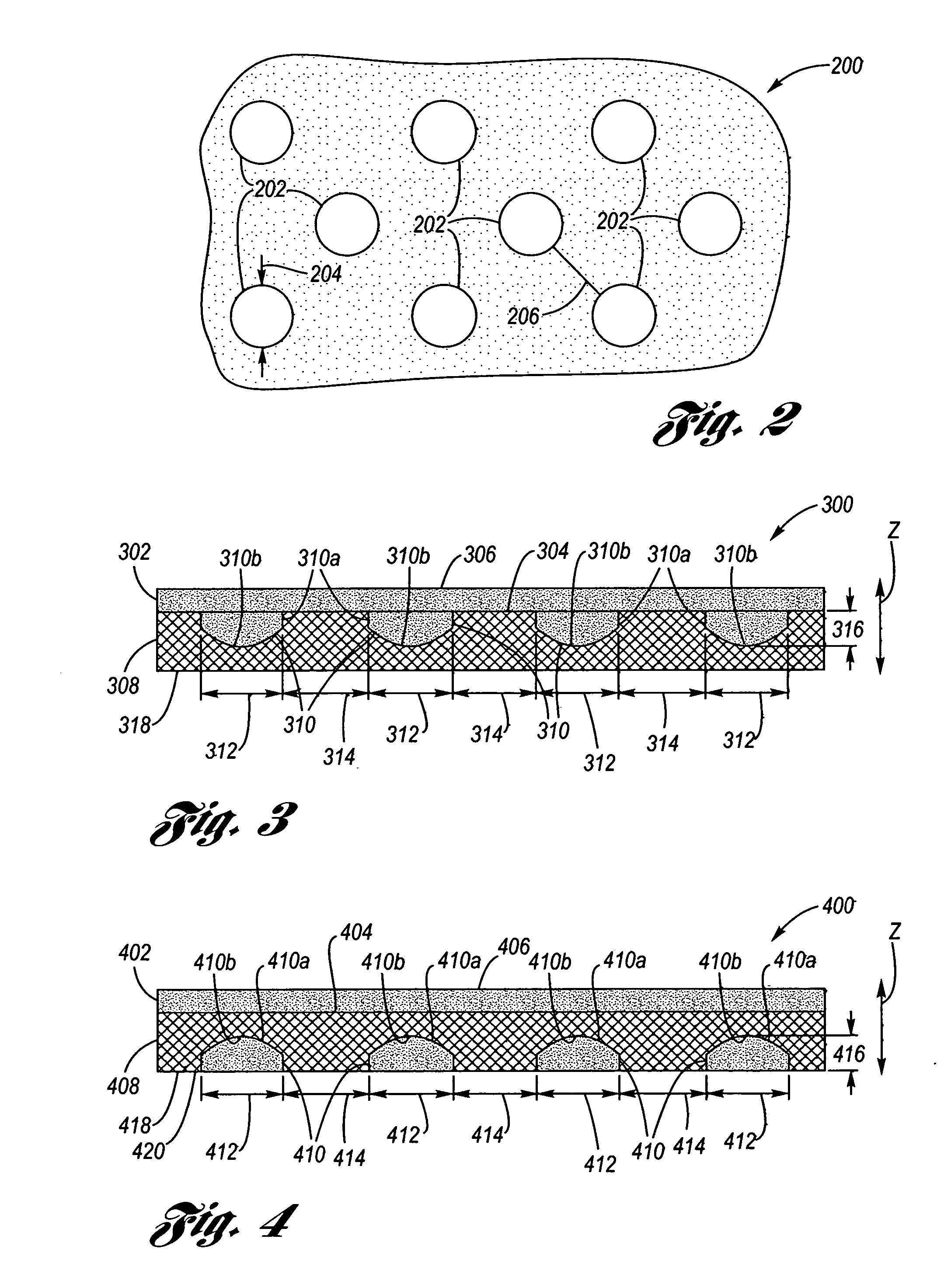
[0038]FIG. 2 depicts a mask 200 containing a geometric hole pattern 202 utilized with the first and second preferred embodiments of the present invention wherein the hole size (diameter) 204 is 1 / 16 of an inch and the hole pitch 206 is ⅛ of an inch The hole size 204 and hole pitch 206 are empirically determined in accordance with the properties of the micro-porous media, the diffusion media, and application pressure of the micro-porous media on the surface of the diffusion media as previously described.

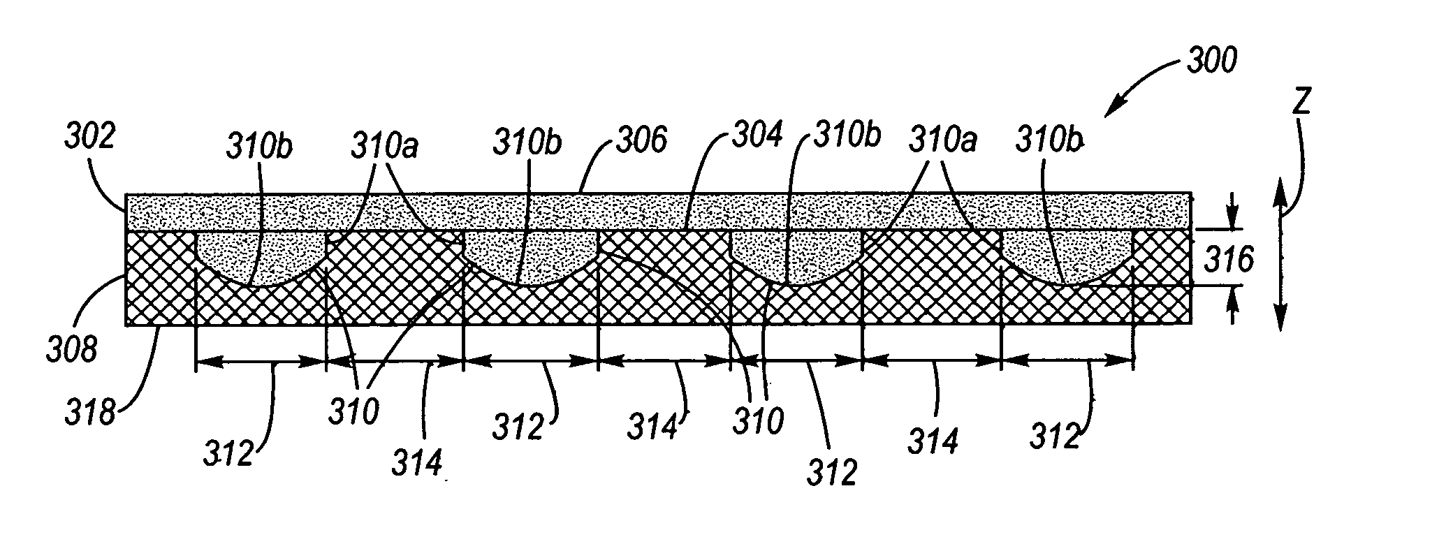
[0039]FIG. 3 is a first example 300, utilizing the mask 200 of FIG. 2, of an implementation of a first preferred embodiment according to the present invention. A continuous MPL 302, consisting of a micro-porous media, is applied to one surface 304 on the electrode side 306 (opposite the flowfield side 318) of at least one or more diffusion media 308 of a fuel cell. A geometric dot pattern 310 of micro-porous media 310a is also introduced into a multiplicity of regions 310b in the sam...


PUM

PropertyMeasurementUnit
porosityaaaaaaaaaa
thicknessesaaaaaaaaaa

Abstract

A diffusion media and micro-porous media combination for a fuel cell. A diffusion layer is composed of a diffusion media and has a first (electrode) side and an opposite second (flowfield) side, wherein at least one of the first and second sides has a geometric pattern formed therein comprising a multiplicity of mutually spaced apart regions. A micro-porous media fills the multiplicity of regions and a micro-porous layer composed of the micro-porous media is continuously applied to the first surface.

Description

TECHNICAL FIELD [0001] The present invention relates to fuel cells and, more particularly, to micro-porous layers incorporating non-uniformity of micro-porous media within diffusion media of fuel cells. BACKGROUND OF THE INVENTION [0002] Electrochemical fuel cells convert fuel and oxidant to electricity and reaction product. Solid polymer electrochemical fuel cells generally employ a membrane electrode assembly (“MEA”) comprising a solid polymer electrolyte or ion exchange membrane disposed between two planar electrode diffusion layers or substrates (diffusion media) formed of porous, electrically conductive sheet material, such as carbon fiber paper or carbon cloth. Suitable carbon fiber paper sheet material is available, for example, from Toray Industries, Inc. with grade designations such as TGP090, TGP060 and TGP030 having thicknesses of 0.27 mm, 0.19 mm and 0.10 mm, respectively, and a porosity of approximately 70%. Carbon fiber paper sheet material is also available in other t...

Claims


Application Information

Patent Timeline
Patent Type & Authority Applications(United States)
IPC IPC(8): H01M4/94B05D5/12H01M4/88
CPCH01M8/023Y02E60/50H01M8/04291H01M8/0245
Inventor GOEBEL, STEVEN G.JI, CHUNXINO'HARA, JEANETTE E.
Owner GM GLOBAL TECH OPERATIONS LLC
Why Eureka
Try Eureka