System and method for automatic self-alignment of a surgical laser

a laser and surgical technology, applied in the field of lasers, can solve the problems of affecting the accuracy of positioning the laser beam at the desired location within the patient's eye, and the most time-consuming portions of the laser vision correction procedure, so as to facilitate the alignment of the laser beam, simplify the setting up of the surgical laser, and reduce the intensity of the laser beam

Inactive Publication Date: 2007-03-01
ALCON REFRACTIVEHORIZONS
View PDF8 Cites 19 Cited by
  • Summary
  • Abstract
  • Description
  • Claims
  • Application Information

AI Technical Summary

Benefits of technology

[0012] Another embodiment of the present invention can provide a laser vision correction surgical system. This laser vision correction surgical system can comprise a laser source and beam steering device that are both directed by a system controller. Additionally, an alignment system may be used to align the laser beam. The alignment system, similar to that of previously discussed embodiments, comprises a beam steering device, a partially reflective surface, focusing optics, and an optical detector. The system controller is operable to cause the beam steering device to direct the laser beam along an alignment pathway to specific coordinates on the surface of the optical detector. The alignment pathway between the beam steering device and optical detector may include a partially reflective surface operable to partially reflect the laser beam. Partial reflection reduces the intensity of the laser beam seen by the optical detector. Focusing optics in the alignment pathway optionally focus the partially reflected laser beam on the surface of the optical detector. The system controller compares coordinates associated with the illuminated portion of the optical detector with the coordinates that the laser beam has been directed to in order to generate a position offset. This position offset is then used to align the laser beam.
[0013] The above described embodiments of the present invention, as well as other embodiments, facilitate the alignment of a laser beam within a laser vision correction system. By facilitating the alignment of the laser beam, the embodiments of this invention may also simplify the set up of the surgical laser, such as an excimer laser, and help reduce the setup time for a surgical procedure. Additionally, the embodiments of the present invention facilitate more frequent alignment of the laser beam, thus allowing laser vision correction procedures to be performed more accurately and in less time.

Problems solved by technology

Galvanometers or other like scanning mechanisms, however, may experience temperature-induced drift, which, if not adequately compensated for, may adversely affect the accuracy of positioning the laser beam at desired locations within the patient's eye.
One of the most time consuming portions of a laser vision correction procedure is the set up and alignment of the surgical laser.
Further, laser vision correction procedures often require re-alignment of the laser between patients or even between performing the procedure on an individual patient's two eyes.

Method used


Image

  • System and method for automatic self-alignment of a surgical laser
  • System and method for automatic self-alignment of a surgical laser
  • System and method for automatic self-alignment of a surgical laser

Examples


Embodiment Construction

[0020] Preferred embodiments of the present invention are illustrated in the FIGUREs, like numerals being used to refer to like and corresponding parts of the various drawings.

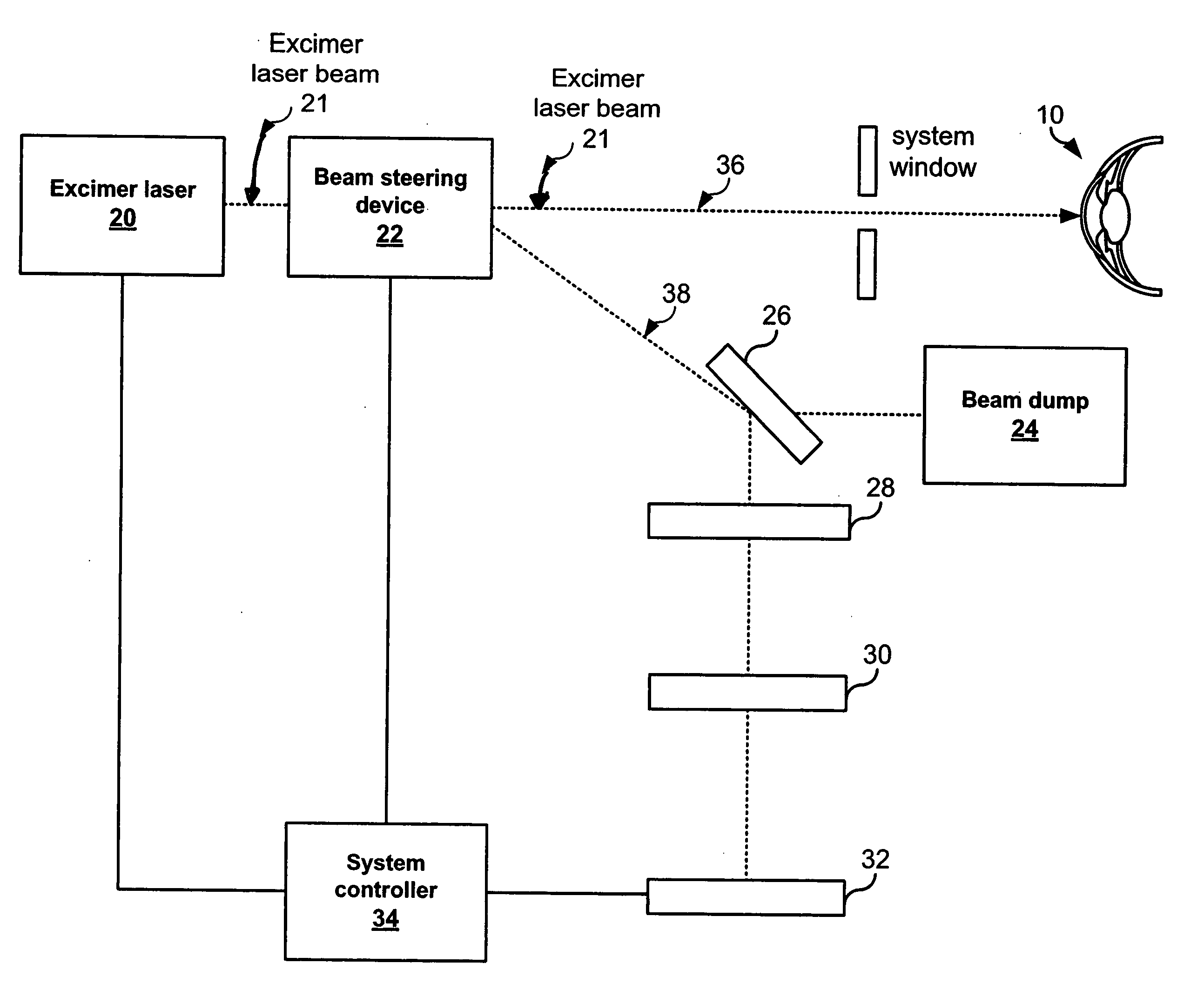
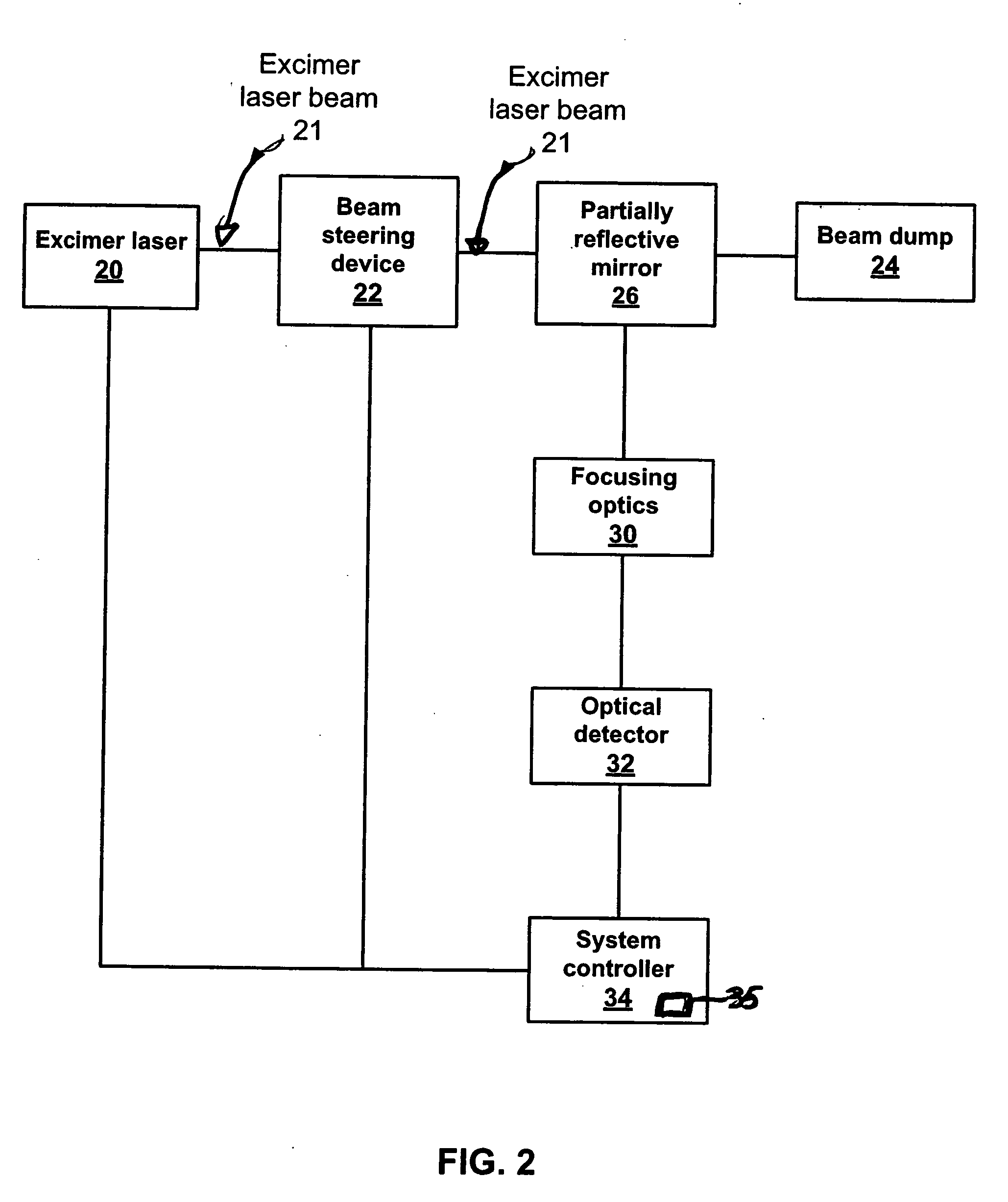
[0021] Embodiments of the present invention substantially address the problem of laser beam misalignment associated with a refractive vision correction procedure performed using a laser, such as an excimer laser. For example, thermal drift associated with galvanometer scanner systems used to position a surgical laser beam can effectively misalign the treatment beam used for such a procedure. Misalignment of the treatment laser beam would likely result in what is referred to as a “de-centered ablation”. Angular drift within a laser itself produces a similar phenomenon. Embodiments of the present invention address both galvanometer and laser drift by providing for automatic alignment of the origin location of a laser vision correction system using a quad-cell, CCD or other like optical detector.

[0022] In perfo...


PUM


Abstract

Embodiments of the present invention provide an alignment system operable to align a laser associated with a laser vision correction system. One embodiment of the alignment system comprises a laser source, a beam steering device, a system controller, a partially reflective surface, focusing optics, and an optical detector. The laser source generates a laser beam that the beam steering device receives and redirects along either a surgical pathway or an alignment pathway. The system controller couples to the beam steering device and directs the beam steering device to choose which pathway to be utilized. Additionally, the system controller may control the pulse repetition rate, intensity, beam profile and alignment of the laser beam. The partially reflective surface, within the alignment pathway, partially reflects the laser beam towards alignment coordinates on the surface of the optical detector. Focusing optics, if needed, may further be utilized to focus the partially reflected laser beam on the surface of the optical detector. The optical detector senses the coordinates associated with the illuminated portion of the surface of the optical detector. The system controller compares the coordinates associated with the alignment coordinates and the sensed coordinates and generates a position offset which is used to align the laser beam / steering device.

Description

CROSS-REFERENCE TO RELATED APPLICATIONS [0001] This application claims priority under 35 U.S.C. §119 to U.S. Provisional Patent Application No. 60 / 713,201, filed Aug. 31, 2005, the entire contents of which are incorporated herein by reference.TECHNICAL FIELD OF THE INVENTION [0002] The present invention relates generally to lasers, and more particularly, to surgical lasers. Even more particularly, the present invention relates to a system and method for aligning a laser beam. BACKGROUND OF THE INVENTION [0003] The application of lasers to vision correction has opened new possibilities for treating nearsightedness, farsightedness, astigmatism, and other conditions of the eye. Specifically, laser technology has allowed the development of modern laser techniques that are collectively known as laser vision correction. [0004] These laser vision correction techniques can be used to reshape the surface or subsurface of an eye 10, as shown in FIG. 1. These techniques may employ a cool beam ...

Claims


Application Information

Patent Timeline
Patent Type & Authority Applications(United States)
IPC IPC(8): G01M19/00G01D3/00G06F19/00G01P21/00G01R35/00A61F9/008G01M99/00
CPCA61B3/00A61F9/00804G06F19/3437A61F2009/00872A61F2009/00846G16H50/50
Inventor GRAY, GARY P.BOWES, JOHN J.OMORI, RICARDO
Owner ALCON REFRACTIVEHORIZONS
Why Eureka
Try Eureka