Non-contact etch annealing of strained layers

a technology of strained layers and etching, which is applied in the direction of polycrystalline material growth, crystal growth process, after-treatment details, etc., can solve the problems of increasing carrier mobility and decreasing lattice dislocation density, reducing mobility, and reducing lattice dislocation density, so as to reduce dislocation density, reduce dislocation, and control the effect of roughness

Inactive Publication Date: 2007-03-08
SILICON GENERAL CORPORATION
View PDF18 Cites 261 Cited by
  • Summary
  • Abstract
  • Description
  • Claims
  • Application Information

AI Technical Summary

Benefits of technology

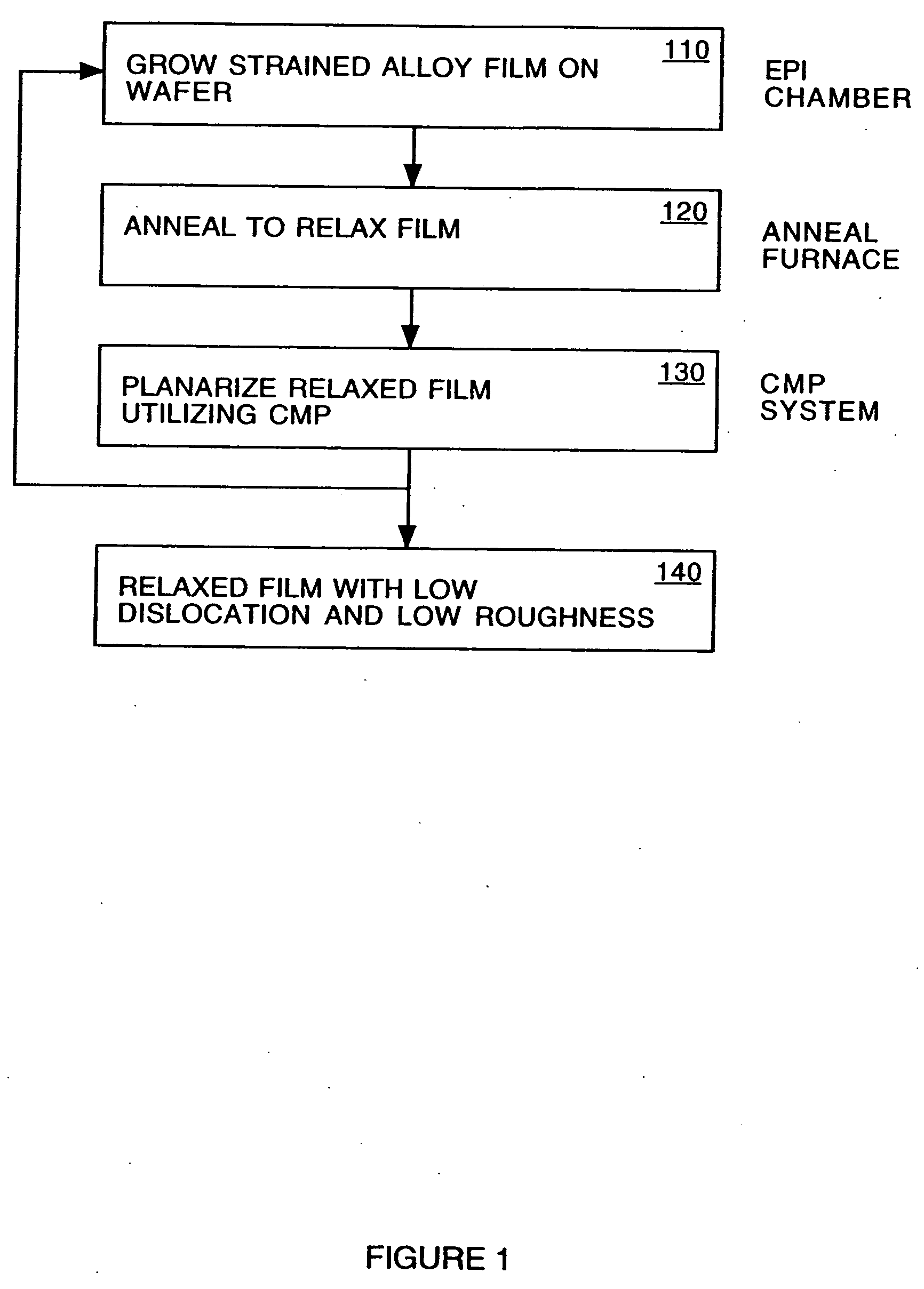
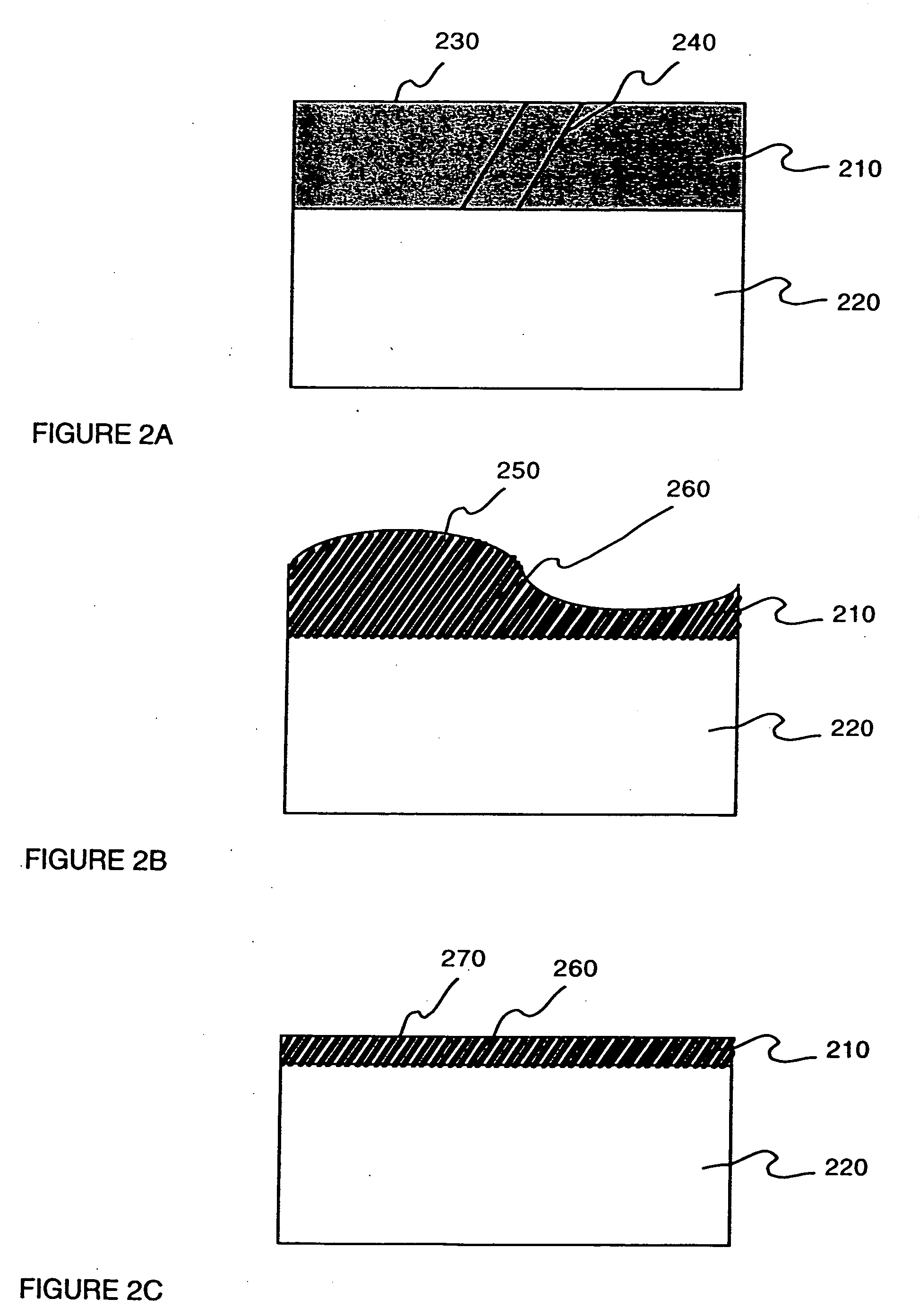
[0019] A method for etch annealing a semiconductor layer is disclosed. In addition to its significant effect in controlling the roughness increases during the relaxation process, the method has the unexpected benefit of substantially reducing dislocations. The reduced dislocation density is advantageous in that carrier mobility and yield are increased.
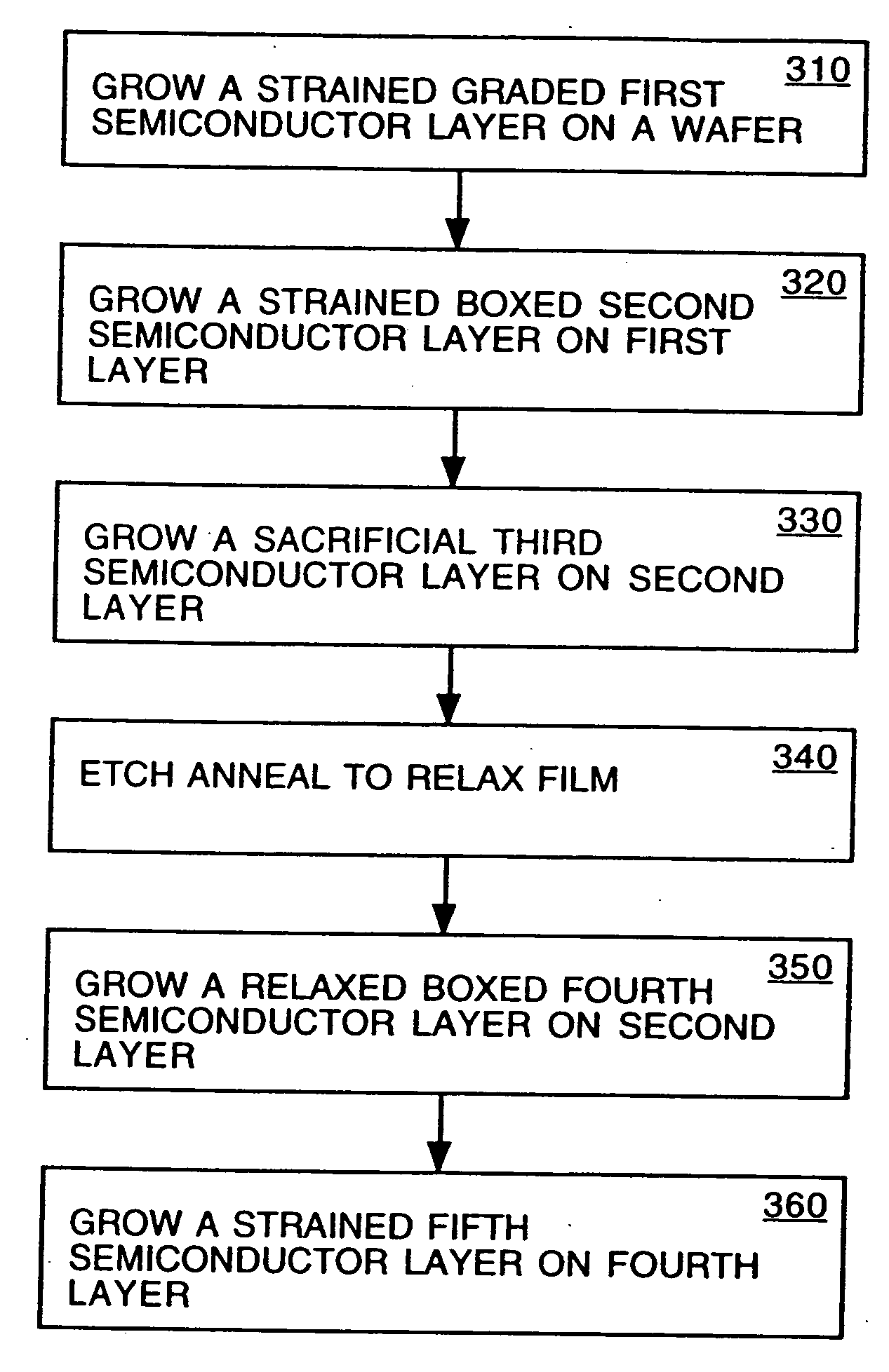
[0020] In one embodiment, a method of forming a strained semiconductor layer is provided. The method comprises growing a strained first semiconductor layer, having a graded dopant profile, on a wafer, having a first lattice constant. The dopant imparts a second lattice constant to the first semiconductor layer. The method further comprises growing a strained boxed second semiconductor layer having the second lattice constant on the first semiconducto

Problems solved by technology

Furthermore, as semiconductor fabrication technology progresses, increasing carrier mobility and decreasing lattice dislocation density become increasingly critical.
A fundamental complication of this mobility enhancement approach is the requirement of a relaxed SiGe film.
Dislocations present on the device layer can tend to short-circuit p-n junctions and also scatter electrons in a uniform n-type crystal, impeding their motion and reducing their mobility.
Dislocations also cause highly localized distortion of the crystal lattice leading to the formation of “trapping” sites where the recombination of positive (holes) and negative (electrons) carriers is enhanced.
Many of the relaxation approaches are therefore tuned to minimize the defect density of the type that can be translated to the device layer and cause device performance degradation, failure and yield losses.
This shallow gradient approach is lower in productivity due to its relatively thick SiGe layer composition and may require numerous growth/anneal cycles to achieve roughness and dislocation goals.
Howev

Method used


Image

  • Non-contact etch annealing of strained layers
  • Non-contact etch annealing of strained layers
  • Non-contact etch annealing of strained layers

Examples


Embodiment Construction

[0028] Reference will now be made in detail to the embodiments of the invention, examples of which are illustrated in the accompanying drawings. While the invention will be described in conjunction with the preferred embodiments, it will be understood that they are not intended to limit the invention to these embodiments. On the contrary, the invention is intended to cover alternatives, modifications and equivalents, which may be included within the spirit and scope of the invention as defined by the appended claims. Furthermore, in the following detailed description of the present invention, numerous specific details are set forth in order to provide a thorough understanding of the present invention. However, it will be obvious to one of ordinary skill in the art that the present invention may be practiced without these specific details. In other instances, well-known methods, procedures, components, and circuits have not been described in detail as not to unnecessarily obscure asp...


PUM


Abstract

The present invention provides a method of forming a strained semiconductor layer. The method comprises growing a strained first semiconductor layer, having a graded dopant profile, on a wafer, having a first lattice constant. The dopant imparts a second lattice constant to the first semiconductor layer. The method further comprises growing a strained boxed second semiconductor layer having the second lattice constant on the first semiconductor layer and growing a sacrificial third semiconductor layer having the first lattice constant on the second semiconductor layer. The method further comprises etch annealing the third and second semiconductor layer, wherein the third semiconductor layer is removed and the second semiconductor layer is relaxed. The method may further comprises growing a fourth semiconductor layer having the second lattice constant on the second semiconductor layer, wherein the fourth semiconductor layer is relaxed, and growing a strained fifth semiconductor layer having the first semiconductor lattice constant on the fourth semiconductor layer. The method controls the surface roughness of the semiconductor layers. The method also has the unexpected benefit of reducing dislocations in the semiconductor layers.

Description

RELATED APPLICATIONS [0001] This application claims the benefit of U.S. Provisional Application No. 60 / 484,181; filed Jun. 30, 2003, and is a continuation-in-part of U.S. application Ser. No. 10 / 264,393, filed Oct. 4, 2002.FIELD OF THE INVENTION [0002] Embodiments of the present invention relate to controlling the growth and morphology of surface roughness during an annealing and relaxation process of strained films, and more particularly to decreasing surface crystalline dislocations during a relaxation process. BACKGROUND OF THE INVENTION [0003] In the conventional art, many semiconductor device fabrication processes utilize planar surfaces. Furthermore, as semiconductor fabrication technology progresses, increasing carrier mobility and decreasing lattice dislocation density become increasingly critical. Improving device yields by reducing dislocations provides for improved manufacturing efficiencies and cost. [0004] In the conventional art, a silicon layer is used as the active d...

Claims


Application Information

Patent Timeline
IPC IPC(8): C30B13/00C30B33/00H01L21/20H01L21/302H01L21/3065
CPCC30B33/00H01L21/02381H01L21/0243H01L21/0245H01L21/3065H01L21/0251H01L21/02532H01L21/02573H01L21/02658H01L21/02505
Inventor ONG, PHILIPHENLEY, FRANCOISMALIK, IGOR
Owner SILICON GENERAL CORPORATION
Why Eureka
Try Eureka