Temporary stents and stent-grafts

a technology of stents and grafts, which is applied in the field of temporary stents and stent grafts, can solve the problems of affecting the applicability of surgical operations, affecting the quality of surgical procedures, and affecting the quality of surgical procedures, and achieves the effect of small diameter

Inactive Publication Date: 2007-03-08
ISHIMARU SHIN +1
View PDF7 Cites 94 Cited by
  • Summary
  • Abstract
  • Description
  • Claims
  • Application Information

AI Technical Summary

Benefits of technology

[0044] According to the invention as set forth in claim 11 of the appended claims, the cylindrically shaped graft is configured to cover the stent of any one of claims 1-10 in the area ranging between the first stent body and the second stent body in the temporary stent-graft. That is to say, this stent-graft is characterized by “a middle strut maintained in a contracted configuration” which is located between the first and second stent bodies each having conventional loosely-interlocked knitted structures, and has a smaller diameter than the first and second stent bodies. Owing to these characteristics, even if the stent-graft is to be positioned within the sharply curved internal tubular organ (for example, the aortic arch, the distal aortic arch, the distal descending aorta and the abdominal aorta), it can adapt to the curve in said organ through repeated release and retraction. Furthermore, in case the stent-graft is temporarily positioned in said organ, the middle strut maintained in a contracted configuration can cope with the curve within the internal tubular organ and both the first and second stent bodies can hold their great dilating forces, resulting in prevention of inflow of body fluid (for example, blood) from either center or periphery. Accordingly, the stent-graft can be tightly secured to the inner wall of the internal tubular organ with no trauma to the inner wall.
[0045] With respect to an aneurysm occurred within a curved artery and presenting a high risk of developing organ ischemia, the temporary stent-graft as set forth in claim 11 of the appended claims enables one to inspect the risk associated with development of organ ischemia in advance, which has never been done before by conventional technologies. Accordingly, the stent-graft in accordance with the present invention substantially broadens the field which permanent stents or stent-grafts can be applied to, and thus can provide a variety of therapeutic advantages for a number of patients suffering from the aneurysm, etc.

Problems solved by technology

An aneurysm is an unfavorable condition resulting from arteriosclerosis, inflammation and other causes that will grow larger and lead to fatal ruptures when left unattended.
Now that medicinal treatments produce hardly any good results, surgical operations using an artificial brood vessel, for example, excision and replacement of bosselation have conventionally been resorted to.
However, this condition appears frequently in aged persons and is often associated with disturbances of a variety of organs (such as the brain, heart and liver).
Therefore, applicability of surgical operations, which can often be exorbitant stresses, is limited.
However, conventional stents or stent-grafts proposed so far cannot be retracted and recovered after they have been once released from catheters and allowed to expand on their own.
As such, they present a serious problem that they cannot be recovered from within the blood vessel even after any organic or blood flow disorder has occurred.
In addition, if they have been placed in the wrong place, they are difficult to move to the right place for correction.
However, this can sometimes block up main arteries branching off from the vicinity of the aneurysm, which can lead to other organic disorder.
Occlusion of these arteries can lead to renal and intestinal ischemic dysfunctions.
With a thoracic aortic aneurysm, occlusion of the intercostals artery can cause disturbance of the spinal cord blood flow leading to a serious complication called paraplegia (lower-body motor paralysis).
The conventional temporary stent or stent-graft, during insertion through the sharply curved internal tubular organ (for example, the aortic arch, the distal aortic arch, the distal descending aorta and the abdominal aorta) can be traumatic to the inner wall of the said organ.
As such, the graft portion of the conventional temporary stent or stent-graft can also wrinkle leading to hindrance of blood flow, and if things come to the worst, thrombus formation.
Accordingly, when the conventional temporary stent or stent-graft, after completion of inspection or treatment, is intended to be retracted back into a catheter, the graft portion irritates the inner wall, and thus presents a high risk of unnecessary trauma to the inner wall.
Moreover, even if such a conventional loosely-interlocked knitted stent (not shown) is implanted into the curved internal tubular organ (for example, the aorta), the distal end and the proximal end of the stent are continuously deformed so that the stent cannot be sufficiently expanded.
Thus, as indicated by the afore-mentioned conventional temporary stent, the stent also cannot enlarge the area of stenosis sufficiently.

Method used


Image

  • Temporary stents and stent-grafts
  • Temporary stents and stent-grafts
  • Temporary stents and stent-grafts

Examples


Embodiment Construction

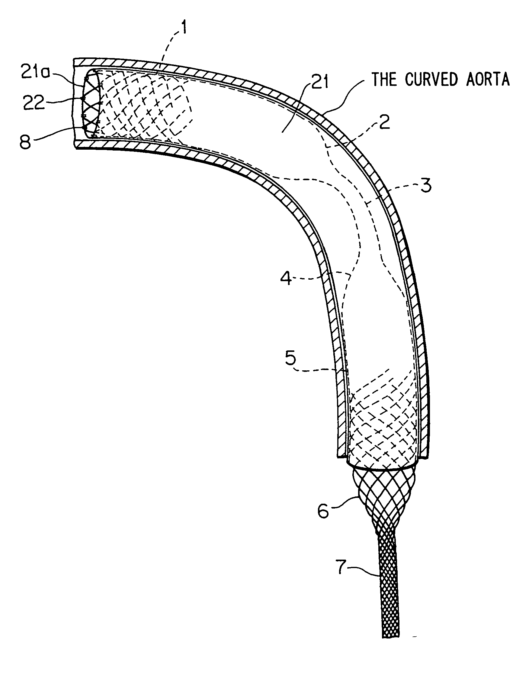
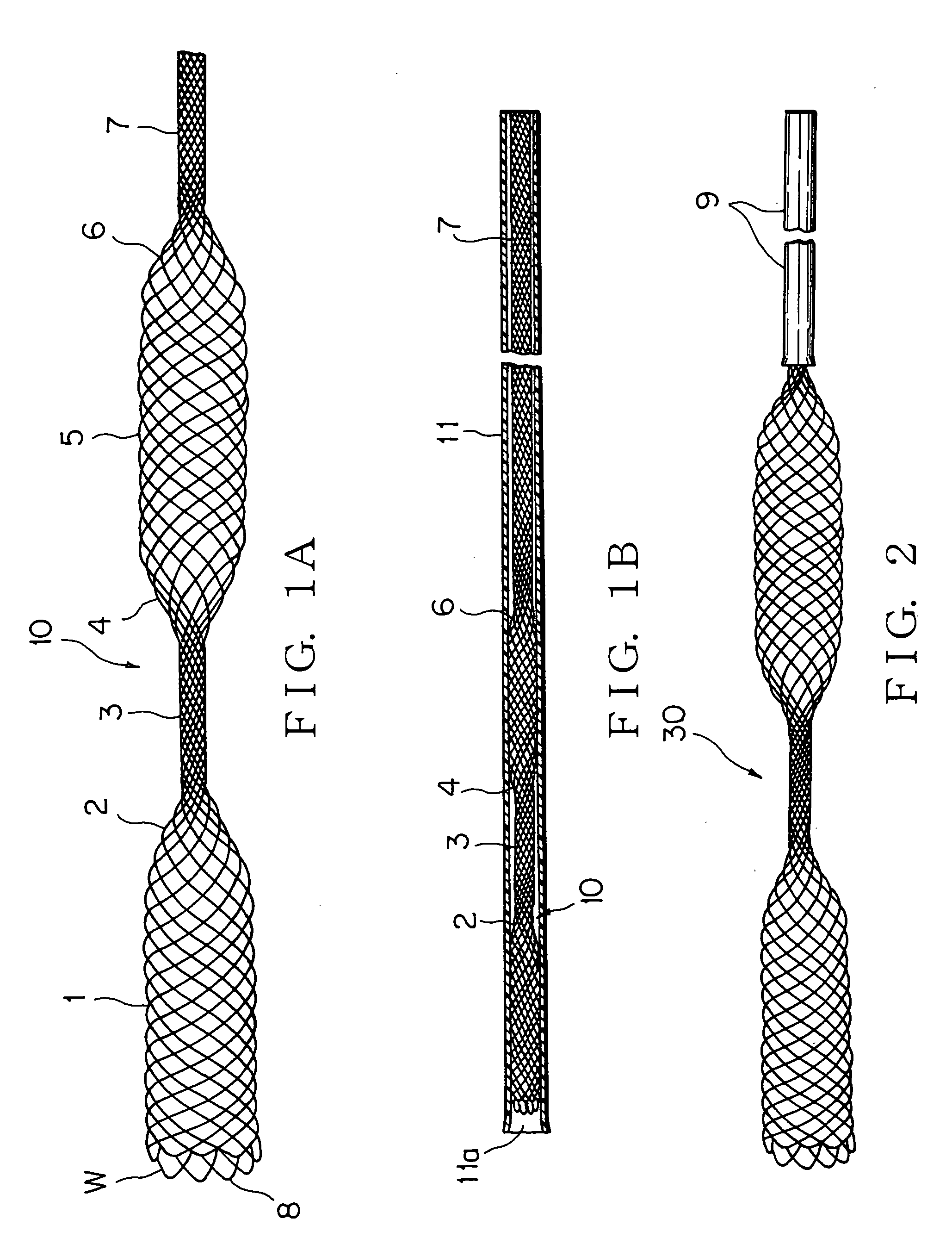
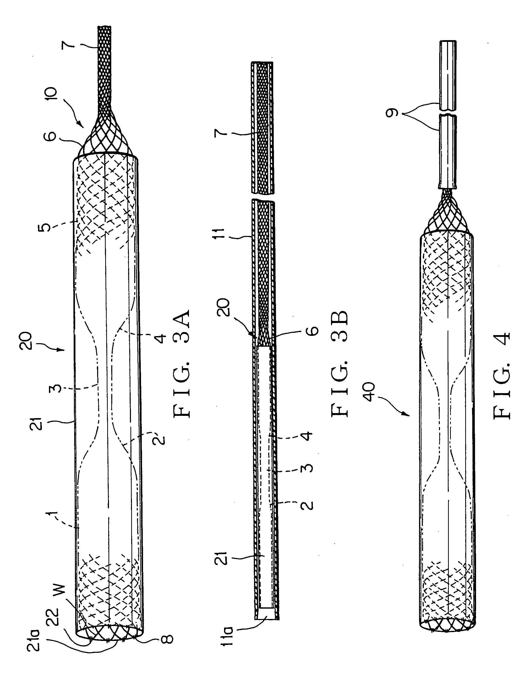
[0050] The present invention will now be described by way of example with reference to the accompanying figures. FIGS. 1A and 1B are illustrations of one embodiment of the temporary stent in accordance with the present invention. FIG. 1A is an illustration of the temporary stent, and FIG. 1B is an illustration of the temporary stent which has been contained in a catheter. FIG. 2 is an illustration of another embodiment of the temporary stent in accordance with the present invention. FIGS. 3A and 3B are illustrations of one embodiment of the temporary stent-graft in accordance with the present invention. FIG. 3A is an illustration of the temporary stent-graft, and FIG. 3B is an illustration of the temporary stent-graft which has been contained in a catheter. FIG. 4 is an illustration of another embodiment of the temporary stent-graft in accordance with the present invention. FIG. 5 is an illustration of the temporary stent-graft as depicted in FIGS. 1A and 1B which has been inserted ...


PUM


Abstract

There is provided A temporary stent comprising a first contractible and expandable stent body having a loosely-interlocked knitted structure formed by twisting at least one filament W in a spiral fashion and being configured to be expanded to form a cylindrical shape as a normal state; a first contractible and expandable proximal end configured to be expanded to form a tapered shape as a normal state; a middle strut maintained in a contracted configuration; a second contractible and expandable proximal end configured to be expanded to form a tapered shape as a normal state; a second contractible and expandable stent body configured to be expanded to form a cylindrical shape as a normal state; a third contractible and expandable proximal end configured to be expanded to form a tapered shape as a normal state; and a strut, in serial order. The filament W is formed of, for example, a shape-memory material.

Description

TECHNICAL FIELD [0001] This invention relates to temporarily locating type stents and stent-grafts for use in inspection of stenotic artery diseases, expansive arterial diseases such as an aneurysm or any other diseases, and in emergency situation, and more particularly to temporarily locating type stents and stent-grafts for use in 1) checking if the placement of a permanent stent involves any risk of occurring hindrance of blood flow, 2) ensuring an adequate inner diameter in the area of stenosis within a tubular organ such as an artery, 3) temporarily closing off rhagades occurred in the inner wall of a tubular organ such as an artery, and 4) temporary hemostasis within a blood vessel in case of emergency. BACKGROUND ART [0002] An aneurysm is an unfavorable condition resulting from arteriosclerosis, inflammation and other causes that will grow larger and lead to fatal ruptures when left unattended. Now that medicinal treatments produce hardly any good results, surgical operations...

Claims


Application Information

Patent Timeline
Patent Type & Authority Applications(United States)
IPC IPC(8): A61M29/00A61F2/90A61F2/00A61F2/06A61F2/07A61M29/02
CPCA61F2/07A61F2/90A61F2002/9528A61F2230/0078A61F2250/0059A61F2002/075A61F2250/0039
Inventor ISHIMARU, SHINKITAMURA, YOSHIRO
Owner ISHIMARU SHIN
Why Eureka
Try Eureka