
Gear manufacturing machine and process for the operation of such a gear manufacturing machine

a manufacturing machine and gear technology, applied in the direction of gear teeth, gear cutting machines, maintenance and safety accessories, etc., can solve the problems of affecting reducing the service life of the finished machine, so as to achieve the effect of substantially reducing the idle tim

Active Publication Date: 2007-03-15
REISHAUER
View PDF13 Cites 11 Cited by
  • Summary
  • Abstract
  • Description
  • Claims
  • Application Information

AI Technical Summary

Benefits of technology

[0008] An object of the present invention is to create a gear manufacturing machine with which, in spite of the modest amount of devices employed, the idle time is substantially shortened, the loading elements are essentially protected from coolant / lubrication media and swarf, and the finished parts are de-oiled before leaving the machine, and also to provide a process for operating the machine. Included in the set task it should moreover be possible to present a solution for the automation of a machine by which, by means of connecting a separate loading module, minimum resources and minimum modifications are required to convert a hand loaded machine to a machine with a high performance automatic work piece loader, without losing the advantages of an integrated system, such as ease of transport as a complete unit, use of the operating media and control systems of the machine etc.
[0009] According to the invention the object is achieved by the entirety of the features in the claims 1 and 20. The core of the invention resides in designing the transfer platform as a centrifuge station. This provides the ability to clean the finished parts in an easy and time-saving manner within the machine immediately after machining.
[0013] For keeping the transfer area clean it is of advantage to provide a lowerable splash guard in the transfer area to cover the transfer platform during centrifuging, in particular in the form of a hood lowerable over the finished work piece.
[0019] The oil mist and splash proof separation of the areas by the partitioning wall is facilitated if the swivel shaft carrying the swivel arms is cylinder shaped, the swivel shaft bearing the swivel arms being preferably located at both ends for rotation and axial displacement. For optimum sealing, the edges of the loading doors contacting the swept surface of the swivel shaft are provided with lip seals.
[0020] In order to facilitate the loading and unloading of the transfer platform, it is an advantage if the transfer platform is arranged on a slide retractable out of the transfer area for loading and unloading from above.

Problems solved by technology

Gear tooth machining is a relatively expensive process in the field of gear unit production.
Nowadays with the masses of gears being produced, the pure machining times often exceed the idle times by a negligible amount only—this not least due to the very unfavorable conditions for work piece handling, since the oils used in the process for cooling and lubrication, and the fine swarf produced by the machining operation are detrimental to a trouble free and exact loading of the machine.
The disadvantage of this method is that the loading elements are totally exposed to the coolant / lubricant and the swarf precipitation, and that the finish machined work piece is very oily from the machining operation and is forwarded in this condition to the follow-up system.
The disadvantages of these solutions are the relatively large amount of apparatus required, the sensitivity to vibration, and the relative inaccuracy of work piece positioning due to the loading system being mostly located way outside the machine, and here again the discharge of oily dripping workpieces.
In medium and small series production however, where the machine is setted up relatively frequently, automatic work piece loading is often not economic due to set up costs.
In the case of the known solutions with rapid integrated loading system, the constructional deviations from the relevant standard machine with manual loading are so great however, that the high demands on a high performance automation cannot be fulfilled by the simple supplementation of the standard machine with a work piece loader.

Method used


Image

  • Gear manufacturing machine and process for the operation of such a gear manufacturing machine
  • Gear manufacturing machine and process for the operation of such a gear manufacturing machine
  • Gear manufacturing machine and process for the operation of such a gear manufacturing machine

Examples


Embodiment Construction

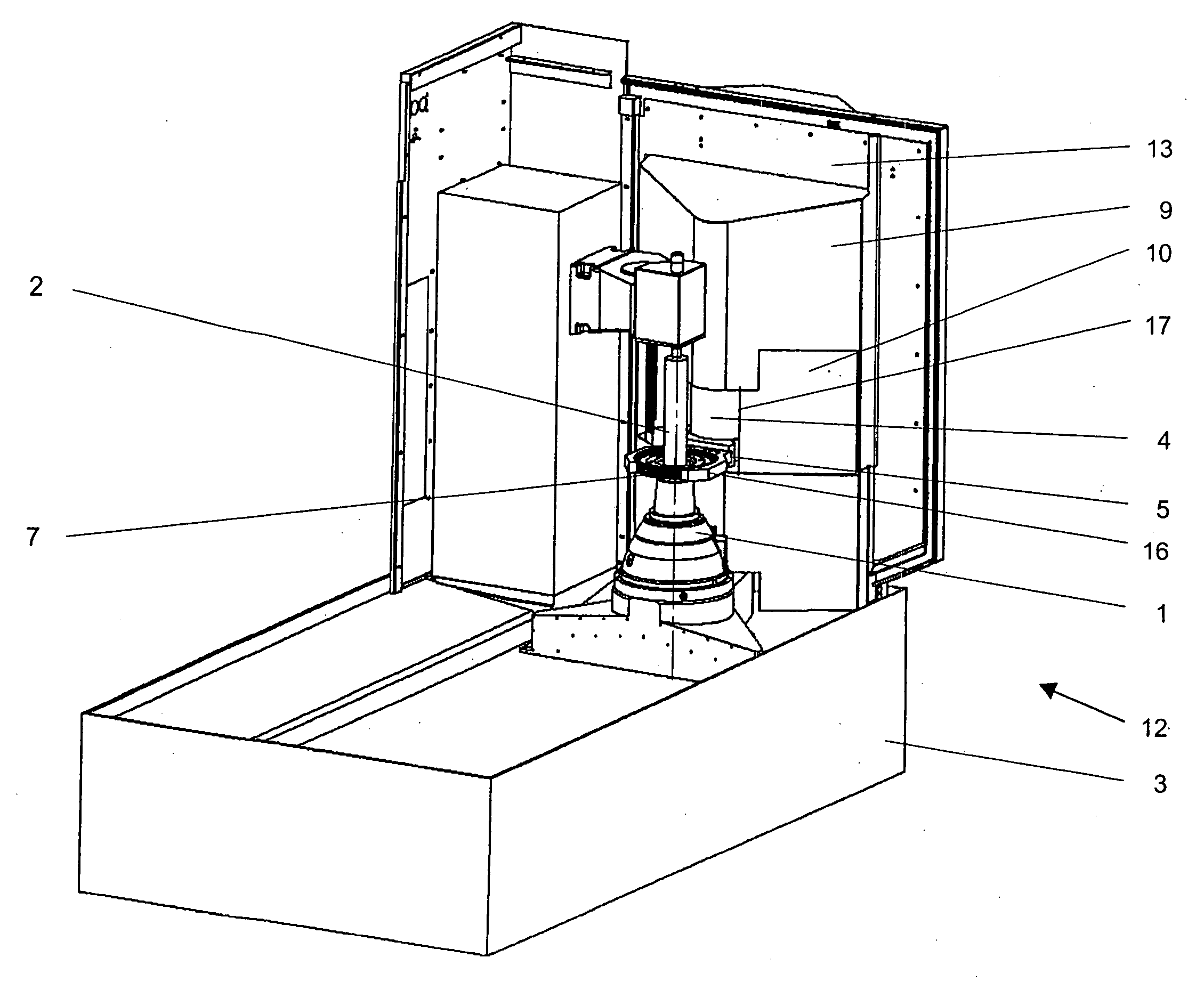
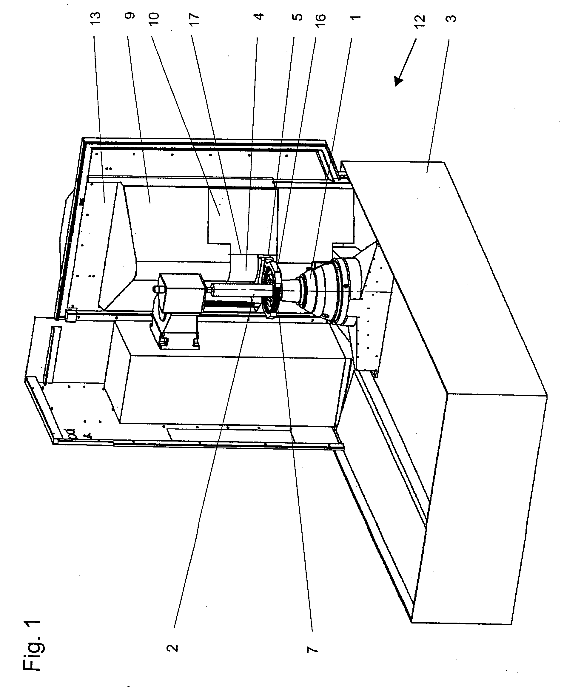
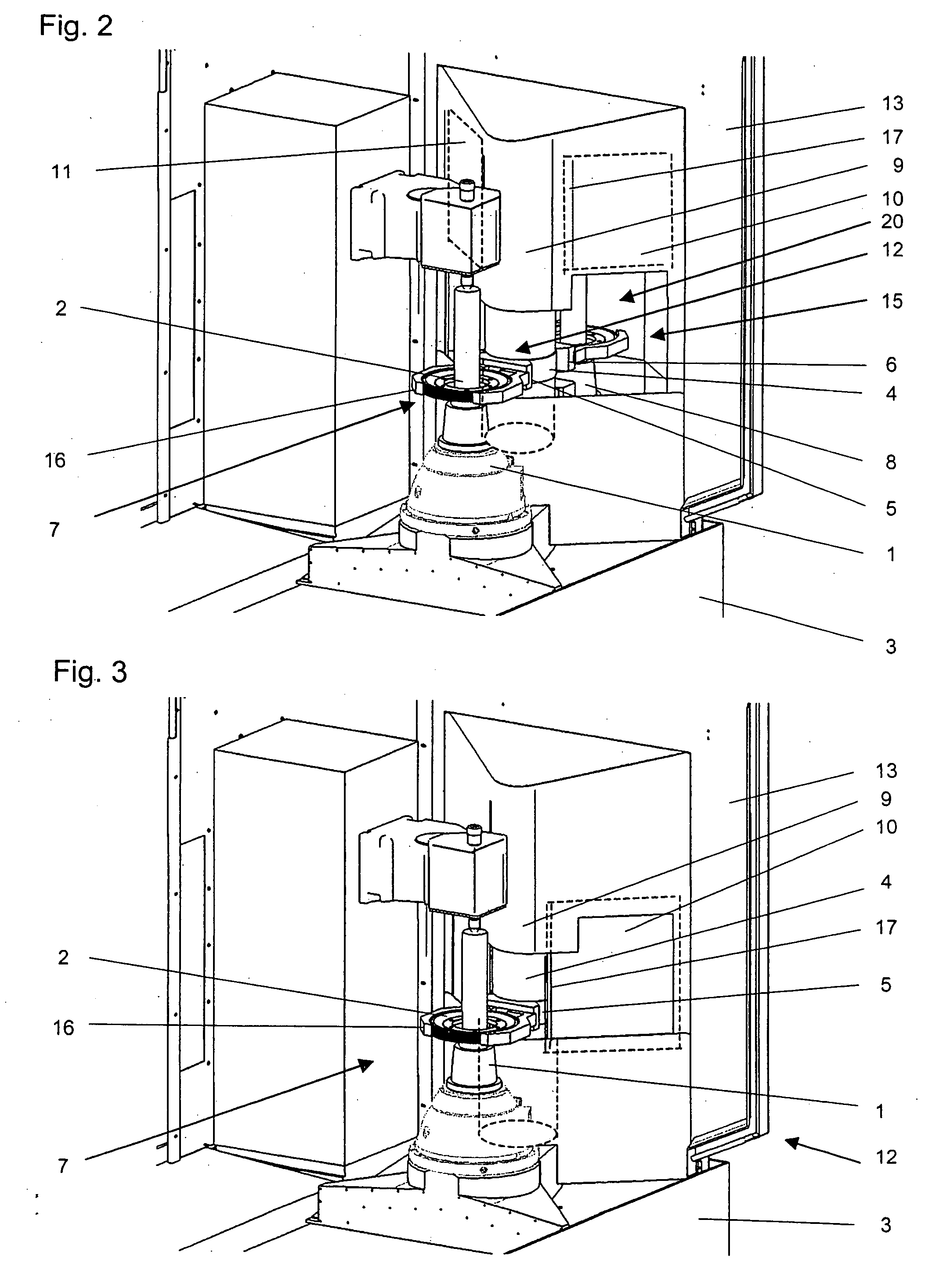
[0032] The invention is described in detail using the example of a tooth flank grinding machine. FIGS. 1 and 2 show diagrammatic views of the work piece sector of the area inside the machine. Clamped on a work spindle 1 located in the machine bed 3 for rotation about a vertical axis is a work piece 2, which is enclosed by a work piece gripper 16. Behind the work piece 2 the machine working area 12 is shut off from the adjacent transfer area (20 in FIG. 2) by a partitioning wall 9. Arranged vertically displaceable in the partitioning wall are two loading doors 10, 11, which are closed in FIGS. 1 and 3, and open in FIG. 2. For the sake of clarity the grinding tool sector of the machine has been omitted.

[0033] The work piece gripper 16 holding the work piece 2 in machining position is the first of two mutually opposite swivel arms 5, 6 designed as work piece grippers, which are fixed to a cylindrical swivel shaft 4 located for rotation about a vertical axis and for raising and lowerin...


PUM

PropertyMeasurementUnit
Areaaaaaaaaaaa
Displacementaaaaaaaaaa

Abstract

The invention concerns a device for the automatic loading of workpieces into a gear manufacturing machine, in particular a hard state finishing machine, by means of a swivel device arranged on the machine, where simultaneous with the machining process of a work piece blank (2) clamped on the work spindle (1) a finish machined work piece (2) on the transfer platform (8) located opposite the work spindle is de-oiled in a work piece loading lock, removed, and a fresh work piece blank fed in. The transfer platform (8) is designed as a centrifuge station.

Description

FIELD OF THE INVENTION [0001] The present invention concerns a gear manufacturing machine, and in particular a hard state finishing machine and a process for the operation of such a gear manufacturing machine. BACKGROUND OF THE INVENTION [0002] Gear tooth machining is a relatively expensive process in the field of gear unit production. This applies already to soft state machining, but in particular to machining after hardening, i.e. to precision hard finish machining. High capacity and high precision machines are required which, according to the high targeted ultimate accuracy of the gear teeth, must clamp the work pieces precisely, align the premachined tooth spaces accurately relative to the machining tool, and finally produce the desired geometry. Machining methods known today are chiefly grinding, but also hard milling, honing, skive hobbing, hard skiving and other processes. [0003] Due to the expensive operation of tooth machining, but in particular hard finish machining, it is...

Claims


Application Information

Patent Timeline
IPC IPC(8): B24B51/00B24B49/00
CPCB23F23/04B23Q11/0042B23Q7/04
Inventor WIRZ, WALTERRONNEBERGER, ERICHJAGER, HELMUT
Owner REISHAUER
Learn More