Corrugated shear panel and anchor interconnect system

a technology of corrugated shear panels and anchors, applied in the construction industry, can solve the problems of building collapse, reduced structural strength, and low structural strength of the corrugated shear panel, and achieve the effect of greater resistance to shear

Inactive Publication Date: 2007-03-22
MUELLER LEE W
View PDF51 Cites 21 Cited by
  • Summary
  • Abstract
  • Description
  • Claims
  • Application Information

AI Technical Summary

Benefits of technology

[0059] In yet another aspect of the invention, a wall assembly interconnection an upper portion of a building to a foundation. The assembly comprising of a plurality of vertical studs distributed along the wall assembly. A shear panel positioned between two adjacent vertical studs at least one location. The panel has a first and second outer edges and a central portion interposed therebetwee

Problems solved by technology

However, the rectangular geometry of the wall frame provides minimal strength when subjected to a combination of axial loading and lateral forces applied horizontally at the top or bottom of the frame wall.
Such a combined force, as occasioned by seismic or high wind events, tends to cause a racking motion between the top and bottom of the wall, and may cause damage ranging from cracks in the wall's surface finish materials to complete structural failure of the wall resulting in a building collapse.
While the conventional, two-dimensional, planar-sheet diaphragm shear panel construction does provide rigidity for the light frame walls and does provide resistance against shear forces, conventional field constructed shear panels do have some drawbacks both in terms of method-of-construction and systems performance.
The drawbacks relating to method-of-construction pertain to the inherent potential for poor quality control in any field constructed assembly, especially where the efficacy of a system is depe

Method used


Image

  • Corrugated shear panel and anchor interconnect system
  • Corrugated shear panel and anchor interconnect system
  • Corrugated shear panel and anchor interconnect system

Examples


Embodiment Construction

[0121] Reference will now be made to the drawings wherein like numerals refer to like parts throughout. FIGS. 1 through 6 relate to embodiments of the invention that use one design of a chord that forms various structures described below. FIGS. 7 through 12 relate to embodiments of the invention that use another design of the chord. It will be appreciated that the chords of different designs both afford advantages in a substantially similar manner that is described below.

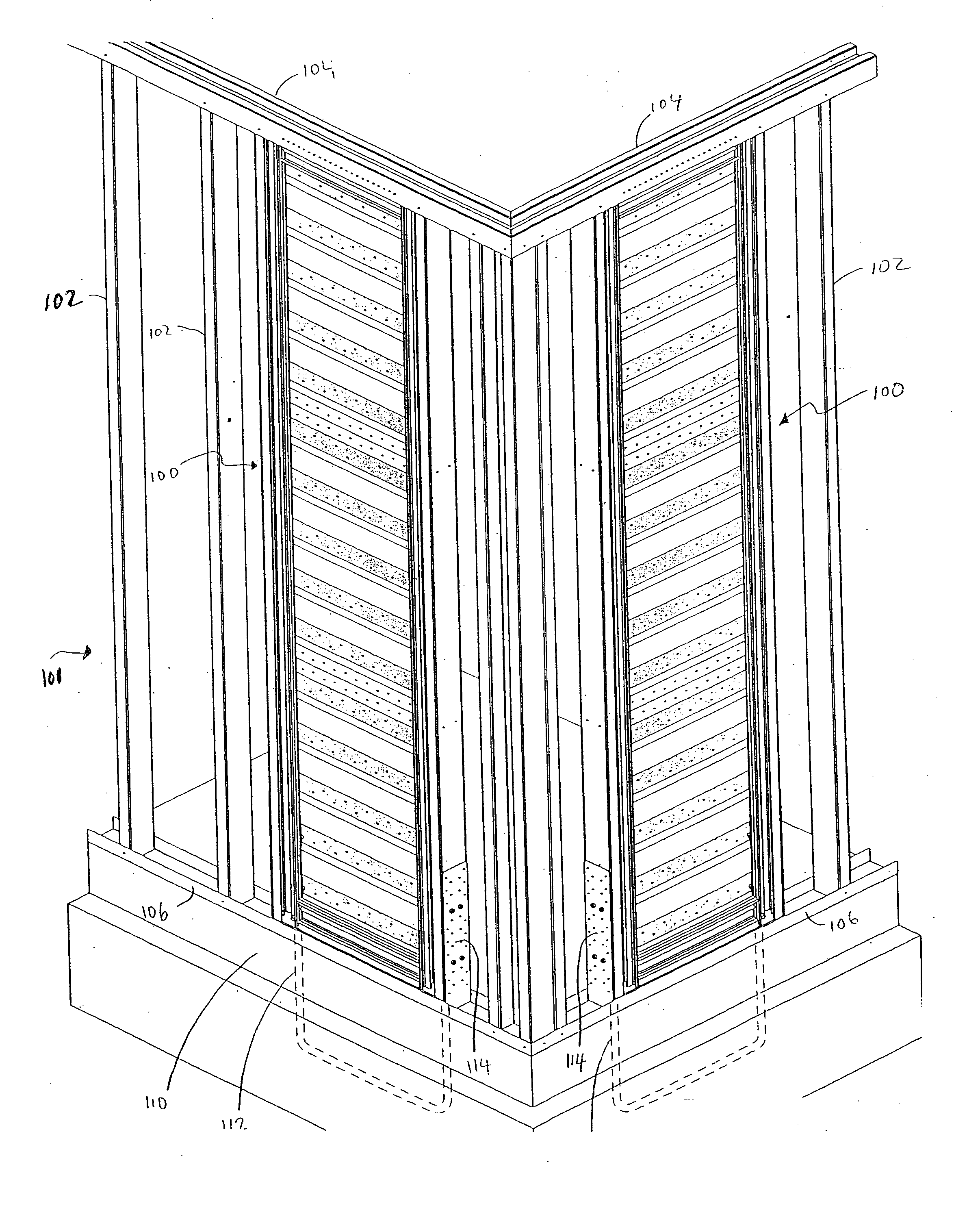
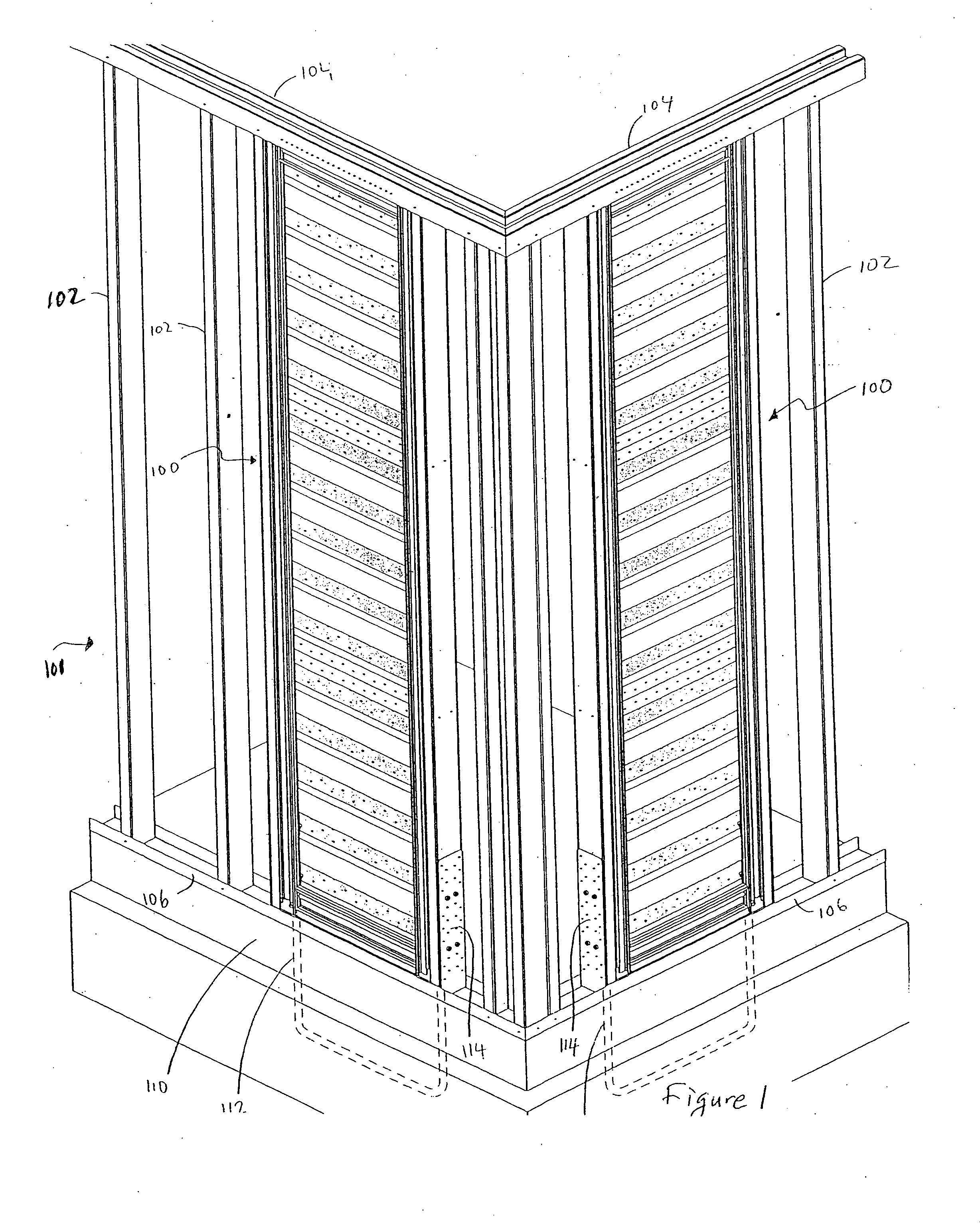
[0122]FIG. 1 is a perspective view of two adjoining wall frames 101 joined at a corner. The wall frame 101 comprises a plurality of vertical chords 102 that are secured at the top by a horizontal chord comprising an M-track 104, and at the bottom by a bottom track 106. In this embodiment, the chords 102, 104 are steel; however, a person of ordinary skill in the art will appreciate that they can be made of a number of different materials, including wood, without departing from the spirit of the invention. The wall f...


PUM


Abstract

A system for inhibiting unwanted movement between a building and an underlying foundation, the system including at least one shear panel assembly including corrugated portions and configured to resist bending and twisting distortion and at least one hold-down assembly configured to attach to the at least one shear panel assembly and to attach to at least one anchor member rigidly engaged with an underlying building foundation so as to resist uplift, downward movement, and lateral movement of the at least one attached shear panel assembly, the at least one hold-down assembly configured to provide a range of vertical attachment adjustment to accommodate a range of extended length of the at least one anchor member.

Description

RELATED APPLICATIONS [0001] This application is a continuation in part of U.S. application Ser. No. 09 / 897,740 filed Jun. 29, 2001 and claims thereby the benefit of U.S. Provisional Application No. 60 / 215,290, filed on Jun. 30, 2000BACKGROUND OF THE INVENTION [0002] 1. Field of the Invention [0003] The invention relates to the construction industry and, in particular, concerns a method of providing lateral strengthening of wall structures using factory manufactured, field installed framed corrugated diaphragm shear panels. [0004] 2. Description of the Related Art [0005] In light frame construction, walls are typically constructed using load bearing framing members made from wood or metal. Most often, a series of vertical studs, periodically spaced usually 16″ to 24″ on center, are secured at top and bottom with horizontal members called plates or tracks so as to form a wall frame. The resulting wall frame is capable of vertical load bearing. However, the rectangular geometry of the ...

Claims


Application Information

Patent Timeline
IPC IPC(8): E02D27/00
CPCE02D31/08
Inventor MUELLER, LEE W.
Owner MUELLER LEE W
Why Eureka
Try Eureka