
Iontophoresis device and method of producing the same

a technology of iontophoresis and production method, which is applied in the field of iontophoresis, can solve the problems of difficult automation, difficult to reduce production costs, waste of cutting margin or punching margin, etc., and achieve the effect of reducing material loss

Inactive Publication Date: 2007-03-22
TITI ELLEBEAU INC
View PDF98 Cites 58 Cited by
  • Summary
  • Abstract
  • Description
  • Claims
  • Application Information

AI Technical Summary

Benefits of technology

The patent describes an iontophoresis device and method of producing it that can reduce material loss during production, simplify the production process, enhance production yield, automate production, and lower production cost. The device includes an active electrode structure with a conductive layer, a drug layer, and an ion exchange layer. The method involves applying a coating to the conductive layer and then sequentially adding layers of drug, electrolyte, and ion exchange resin containing an exchange group with a counter ion to the drug ions. This can reduce the movement of ions and improve the stability of the device. The device can also be produced using a counter electrode structure with multiple layers of conductive layers, electrolyte layers, and ion exchange layers. Overall, the device and method described in the patent can improve the efficiency and effectiveness of iontophoresis for drug delivery.

Problems solved by technology

However, in order to produce the above mentioned iontophoresis device 101a, it is necessary to prepare the ion exchange membrane 116 in accordance with the size and shape of the active electrode structure 110a by cutting or punching, with the result that a cutting margin or a punching margin is wasted.
It may thus be difficult to reduce production costs, difficult to automate and difficult to mass produce.
However, the iontophoresis device 101b has problems similar to those described with respect to the iontophoresis device 101a.
For those reasons, it becomes more difficult to achieve the reduction in a production cost, automation of production, or mass production.

Method used


Image

  • Iontophoresis device and method of producing the same
  • Iontophoresis device and method of producing the same
  • Iontophoresis device and method of producing the same

Examples


Embodiment Construction

[0073] In the following description, certain specific details are set forth in order to provide a thorough understanding of various disclosed embodiments. However, one skilled in the relevant art will recognize that embodiments may be practiced without one or more of these specific details, or with other methods, components, materials, etc. In other instances, well-known structures associated with iontophoresis devices, controllers, voltage or current sources and / or membranes have not been shown or described in detail to avoid unnecessarily obscuring descriptions of the embodiments.

[0074] Unless the context requires otherwise, throughout the specification and claims which follow, the word “comprise” and variations thereof, such as, “comprises” and “comprising” are to be construed in an open, inclusive sense, that is as “including, but not limited to.”

[0075] Reference throughout this specification to “one embodiment” or “an embodiment” means that a particular feature, structure or c...


PUM

PropertyMeasurementUnit
polarityaaaaaaaaaa
conductiveaaaaaaaaaa
water-solubleaaaaaaaaaa

Abstract

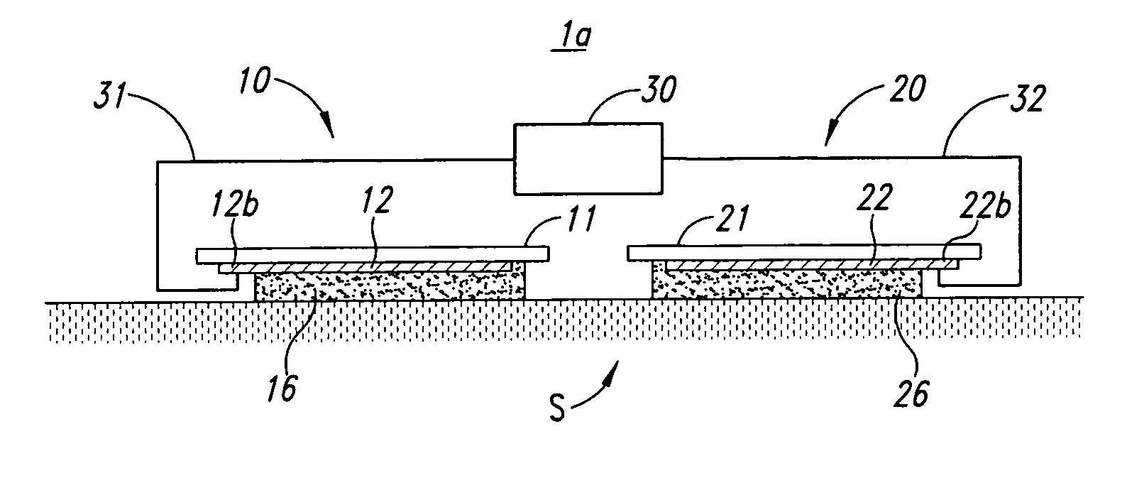
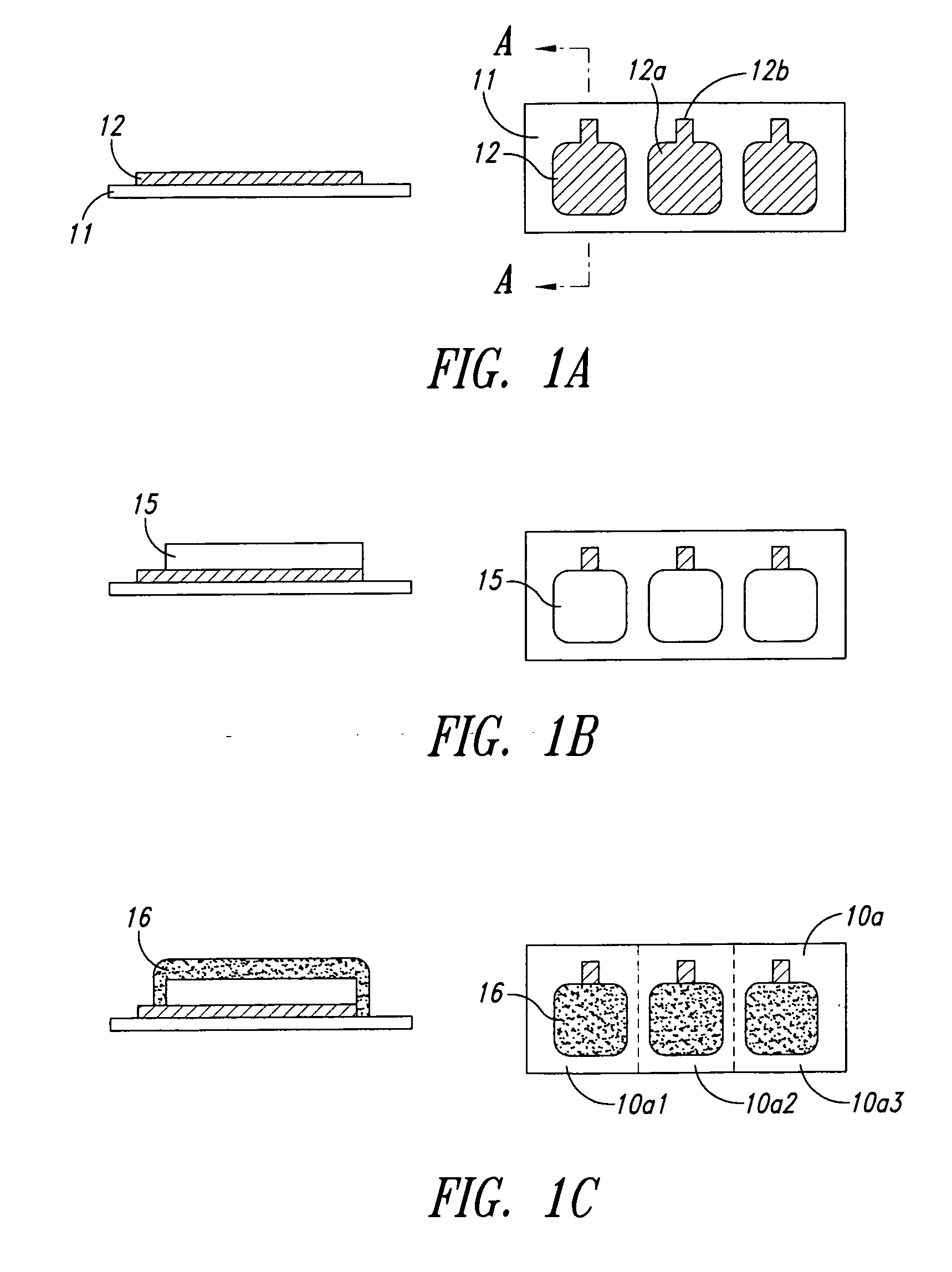
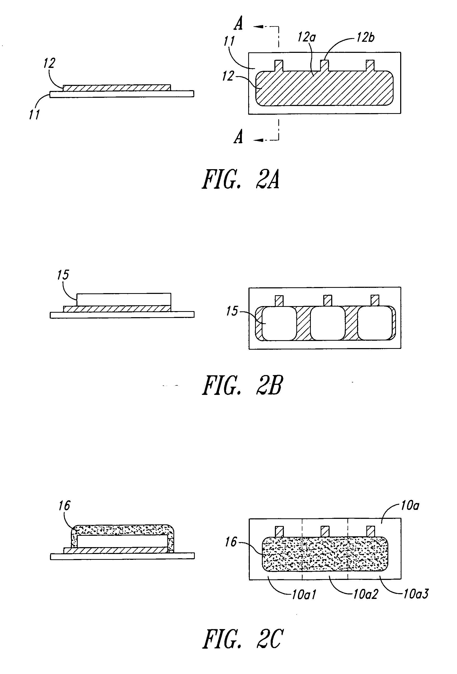
An iontophoresis device and method of producing the same may reduce material loss during the course of production of a conventional iontophoresis device, and may allow for easy automation of production processes and increases in production scale. The iontophoresis device may be used for administering drug ions of a first polarity generated by dissociation of a drug to a living body, and may comprise: a first conductive layer formed on a surface of a first substrate; a drug layer made of a drug coating containing the drug, the drug layer being laminated on the first conductive layer; and a first ion exchange layer made of an ion exchange coating containing an ion exchange resin having an exchange group introduced thereto, the ion exchange group having a counter ion to the first polarity ions, the first ion exchange layer being laminated on the drug layer.

Description

BACKGROUND OF THE INVENTION [0001] 1. Field of the Invention [0002] The present disclosure relates to an iontophoresis device for administering drug ions of a first polarity to a living body and a method of producing the same. [0003] 2. Description of the Related Art [0004] An iontophoresis device generally includes an active electrode structure that holds a drug whose active ingredient dissociates into positive or negative drug ions, and a counter electrode structure that functions as a counter electrode to the active electrode structure. A voltage or electrical potential having the same polarity as that of the drug ions is applied to the active electrode structure under the condition that both structures maintain ion transferring engagement with the skin (or mucosa) of a living body (a human being or an animal), whereby the drug ions are administered to the living body. [0005] Current or electrical potential supplied to the active electrode structure causes the movement of the dru...

Claims


Application Information

Patent Timeline
Patent Type & Authority Applications(United States)
IPC IPC(8): A61N1/30A61L33/00B32B18/00
CPCA61N1/044A61N1/0448A61N1/0444
Inventor TANIOKA, AKIHIKOMATSUMURA, AKIHIKOMATSUMURA, TAKEHIKONAKAYAMA, MIZUOAKIYAMA, HIDERO
Owner TITI ELLEBEAU INC
Learn More