
Electric power steering control device

a control device and power steering technology, applied in the direction of power steering, electric steering, vehicle components, etc., can solve the problems of inability to obtain accurate steering angle information, inability to secure the gate voltage required to turn on the field effect transistor, and inability to obtain accurate current detection values, etc., to achieve the effect of expanding the control range of steering assis

Inactive Publication Date: 2007-03-29
NSK LTD
View PDF4 Cites 18 Cited by
  • Summary
  • Abstract
  • Description
  • Claims
  • Application Information

AI Technical Summary

Benefits of technology

[0015] According to the invention as claimed in claim 1, since the voltage of the in-vehicle battery is adjusted by the control power generating circuit to generate the control power and the generated control power is supplied at least to the steering assist control means, even when the battery voltage is dropped, the control voltage of each apparatus requiring the control power can be secured, and therefore, the advantages of being able to continue a state in which the electric motor is driven to generate a steering assist force can be obtained.
[0016] Further, according to the invention as claimed in claim 2, the voltage of the in-vehicle battery is adjusted by the control power generating circuit to generate the control power and the generated control power is supplied to the power supply step-up circuit. Therefore, even when the battery voltage is dropped, the power supply step-up circuit can step up the voltage to a sufficiently high voltage that can be supplied to the gate drive circuit, and the advantages of being able to continue a state in which the electric motor is driven to generate a steering assist force can be obtained.
[0018] Further, according to the invention as claimed in claim 4, when the battery voltage detection means detects that the battery voltage of the in-vehicle battery is dropped blow the set voltage, the control power generating circuit causes the step-up circuit to step up the voltage up to a voltage required by the control power supply target apparatus so as to generate a control power, and therefore, even in case the battery voltage of the in-vehicle battery is temporarily dropped rapidly, the control voltage can be generated by the control power step-up circuit, and therefore, the advantages of being able to maintain a generating state of the steering assist force can be obtained.
[0019] Further, according to the invention as claimed in claim 5, when the battery voltage of the in-vehicle battery is put into a high voltage state in which the voltage is increased above a set voltage, the control power step-down circuit steps down the voltage to a voltage required in the control power supply target apparatus to generate the control power, and therefore, even in case the battery voltage of the in-vehicle battery is rapidly increased, it is possible to maintain the control voltage within a normal range, and the advantages of being able to suitably drive the electric motor so as to expand a steering assist control range.
[0020] Furthermore, according to the invention as claimed in claims 6 and 7, when the battery voltage of the in-vehicle battery is put into a low voltage state in which the voltage is dropped below a set voltage, the output voltage of the voltage regulator generating the control voltage supplied to the microcomputer is stepped up by the control power step-up circuit, so that an almost constant control voltage can be secured regardless of the fluctuation of the battery voltage, and therefore, the advantages of being able to appropriately drive the electric motor and continuing a generating state of the steering assist force can be obtained.

Problems solved by technology

However, there exists an unsolved problem of the case occurring where when the battery voltage is dropped, the stepped up voltage itself which is outputted from the charge pump is also dropped and the gate voltage required to turn on the field effect transistors is unable to be secured.
Further, if taking a survey of the entire electric power steering control device, for example, there exist such unsolved problems in that, in case a resolver is adopted in order to detect the rotation of the motor, when the battery voltage is dropped, the upper limit side of a resolver signal is cut and distorted under the influence of the voltage dip of the battery, and in a torque sensor also, since an exciting circuit is used when a magnetic signal is converted into an electrical signal, a linear range of this exciting circuit is narrowed down under the influence of the voltage dip of the battery or in a motor current detection circuit for detecting a motor current, though a potential difference at both ends of a shunt resistor is amplified by an operational amplifier, in this case also, it is not possible to obtain an accurate current detection value under the influence of the voltage dip of the battery or in case a steering angle sensor is adopted also, it is not possible to obtain accurate steering angle information under the influence of the voltage dip of the battery.

Method used


Image

  • Electric power steering control device
  • Electric power steering control device
  • Electric power steering control device

Examples


first embodiment

[0031] the present invention will be described below based on the drawings.

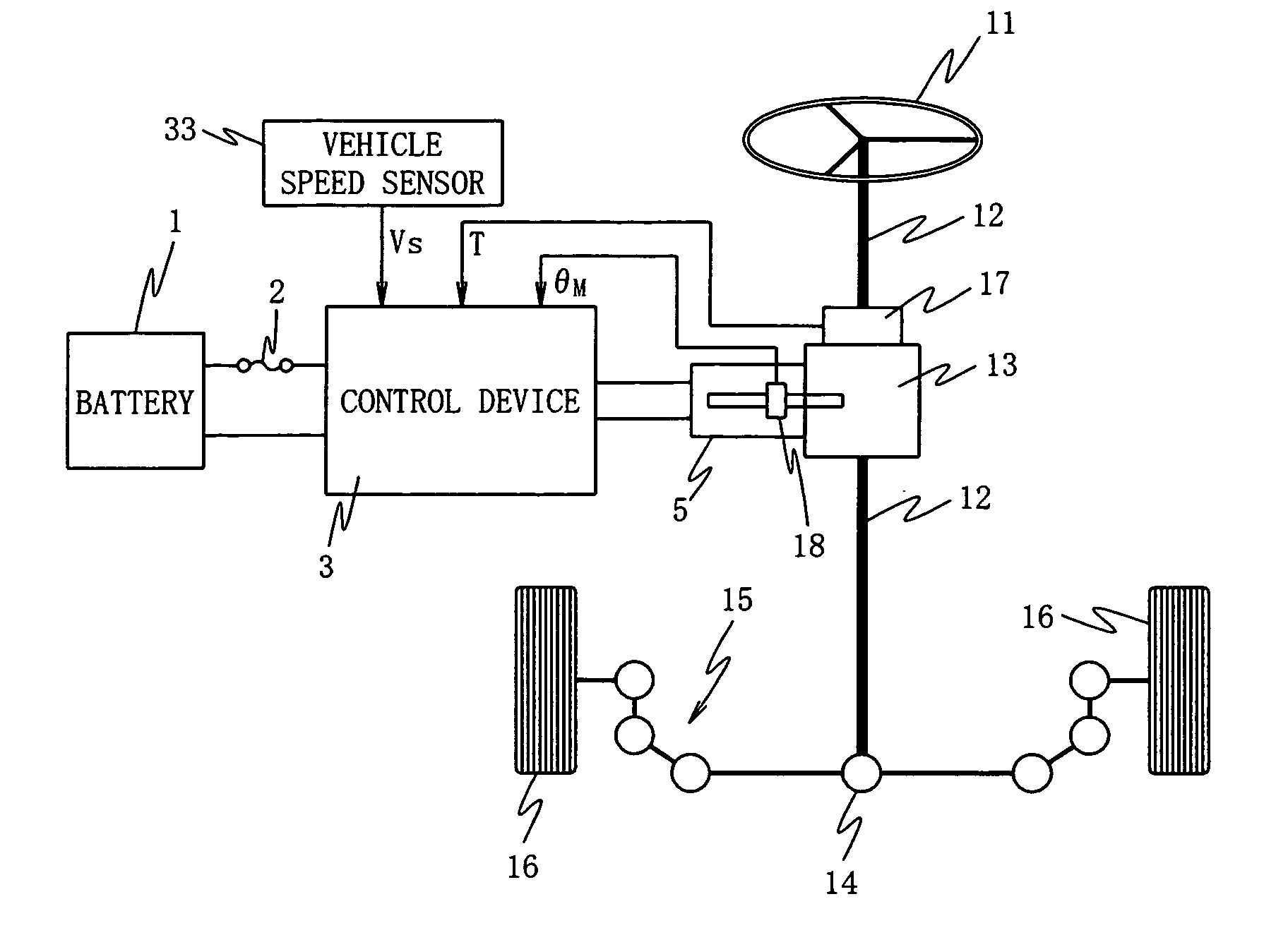
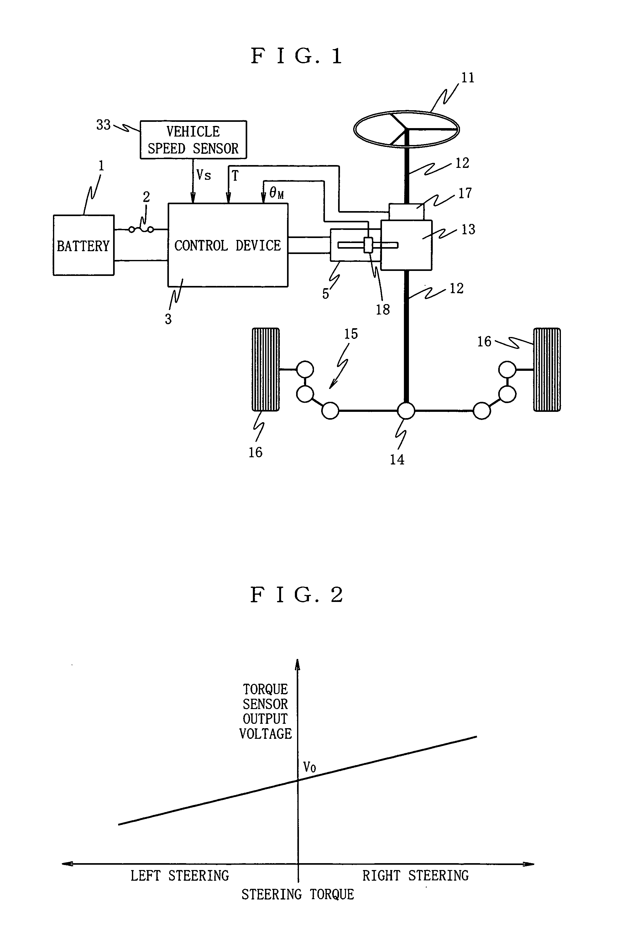
[0032]FIG. 1 is a schematic block diagram showing the first embodiment of an electric power steering control device according to the present invention.

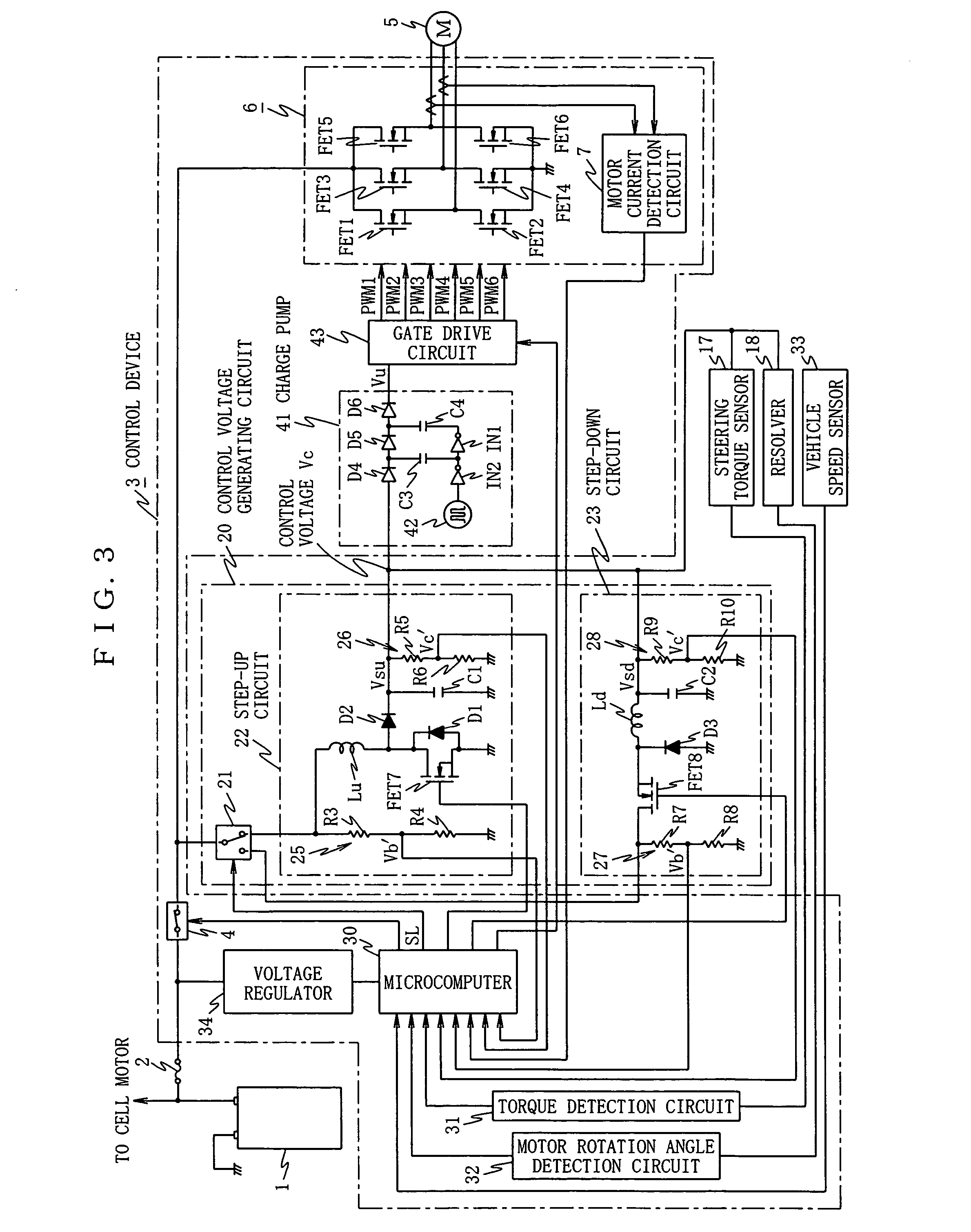
[0033] In the figure, reference numeral 1 denotes a battery of 12V in rated voltage mounted on an ordinary vehicle, and a battery voltage Vb outputted from this battery 1 is inputted to a control device 3, which is a steering assist control means, though a fuse 2. This control device 3 has a motor drive circuit 6 as motor driving means for driving an electric motor 5, which generates a steering assist force for a steering system inputted with the battery voltage Vb through a relay 4 shown in FIG. 3 through the fuse 2.

[0034] Here, the electric motor 5 is constituted by a three-phase AC driven brushless motor, and is operated as a steering assist force generating motor for generating a steering assist force of the electric power steering control device. This el...

second embodiment

[0088] Next, the present invention will be described with reference to FIGS. 9 and 10.

[0089] In this second embodiment, an output voltage of a voltage regulator 34 for supplying a control power supply to a microcomputer 30 is stepped up by a step-up circuit.

[0090] That is, in the second embodiment, as shown in FIG. 9, the selector switch 21 and the step-down circuit 23 in FIG. 3 in the first embodiment are omitted, and except that, in replace of these elements, one end of a reactor Lu of a step-up circuit 22 is connected to the output side of a voltage regulator 34 the second embodiment has the same constitution as FIG. 3, the same reference numerals are attached to the elements corresponding to FIG. 3, and the detailed description thereof will be omitted.

[0091] In this case, in a voltage regulator 34, since the battery voltage can maintain a power supply voltage Vcm regardless of the fluctuation of a battery voltage Vb until the battery voltage is dropped below the power supply v...


PUM


Abstract

Generation of a steering assist force is allowed to continue by securing an appropriate control power without being affected by the fluctuation of a battery voltage. An electric power steering control device comprising steering torque detection means 17 for detecting a steering torque, an electric motor 5 allowed to generate a steering assist force for a steering system, and steering assist control means 3 for controlling the electric motor based on the steering torque detected by the steering torque detection means 17 comprises a control power generating circuit 20 for stepping up a battery voltage of an in-vehicle battery 1 to generate a control power and supplying the generated control power at least to the steering assist control means 3.

Description

BACKGROUND OF THE INVENTION [0001] 1. Field of the Invention [0002] The present invention relates to an electric power steering control device, which comprises a steering torque detection means for detecting a steering torque, an electric motor for generating a steering assist force for a steering system, and steering assist control means for controlling the electric motor based on the steering torque detected by the steering torque detection means. [0003] 2. Description of the Related Art [0004] In general, as an electric power steering control device of this type, there is known, for example, a device in which, from among four field effect transistors constituting an H bridge circuit for driving an electric motor to generate a steering assist force of the electric power steering device, two field effect transistors at a power supply voltage Vcc side are connected to a charge pump, respectively, and by these charge pumps, the power supply voltages Vcc to 2 Vcc are generated and sup...

Claims


Application Information

Patent Timeline
Patent Type & Authority Applications(United States)
IPC IPC(8): B62D5/04
CPCB62D5/046
Inventor MIURA, TOMOHIROMAEDA, MASAHIROITAKURA, YUSUKE
Owner NSK LTD
Learn More