
Method of Making Ceramic Discharge Vessels Using Stereolithography

a technology of ceramic discharge vessels and stereolithography, which is applied in the manufacture of electric discharge tubes/lamps, cold cathode manufacture, electrode systems, etc., can solve the problems of adding significant time and cost to the process, and achieve the effect of reducing time and expens

Inactive Publication Date: 2007-03-29
OSRAM SYLVANIA INC
View PDF5 Cites 34 Cited by
  • Summary
  • Abstract
  • Description
  • Claims
  • Application Information

AI Technical Summary

Benefits of technology

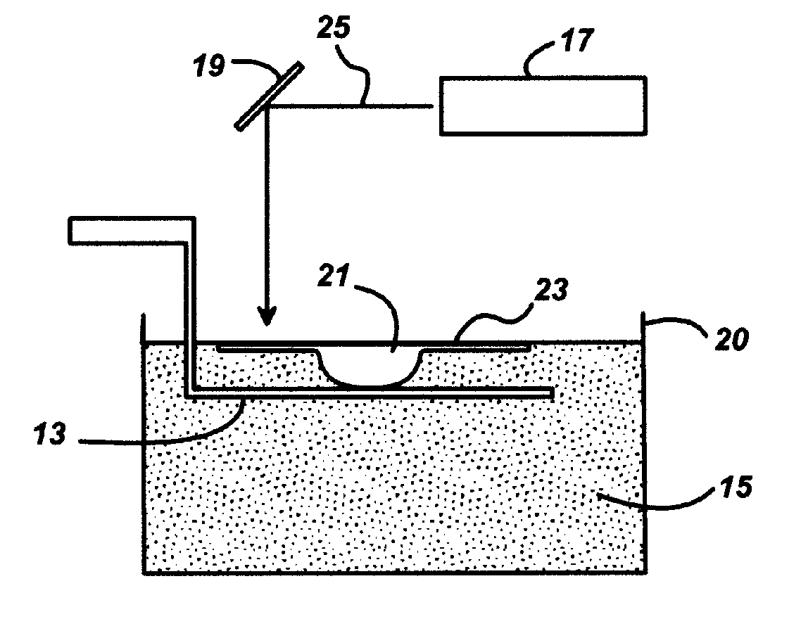
[0010] A major advantage of the invention is that the ceramic discharge vessel is formed without the need for any dies or molds to form the shape. This results in a reduction in time and expense in the fabrication of new discharge vessel designs. The process further allows for the design of more complex discharge vessel shapes which may be impossible or impractical by conventional ceramic-forming processes.
[0011] In accordance with one aspect of the invention, there is provided a method of making a ceramic discharge vessel, comprising: (a) forming a mixture of a ceramic powder, a dispersant, a photoinitiator, and a resin, the mixture having a solids content of at least about 45 volume percent and a viscosity of less than about 50,000 mPa·s; (b) forming a green body having the general shape of the discharge vessel by localized curing of the resin mixture; (c) heating the green body first in an inert atmosphere at a temperature from about 500° C. to about 600° C. followed by heating in an oxygen-containing atmosphere at a temperature from about 500° C. to about 1350° C. to remove the cured resin and form a presintered body; (d) sintering the presintered body to form the ceramic discharge vessel.
[0012] In accordance with another aspect of the invention, there is provided a ceramic-resin mixture for forming ceramic discharge vessels by stereolithography, the mixture consisting of a homogeneous dispersion of a ceramic powder, a dispersant, a photoinitiator, and a resin, the mixture having a solids content of at least 45 volume percent and a viscosity of from about 200 to about 25,000 mPa·s

Problems solved by technology

In the development of new lamp applications, this can add significant time and cost to the process, particularly when several design iterations are required to achieve a lamp with the desired combination of life, light quality and efficacy.

Method used


Image

  • Method of Making Ceramic Discharge Vessels Using Stereolithography
  • Method of Making Ceramic Discharge Vessels Using Stereolithography
  • Method of Making Ceramic Discharge Vessels Using Stereolithography

Examples


example

[0032] A liquid ceramic-resin mixture of 45 vol. % (25.4 wt. %) Al2O3 and 55 vol. % (74.6 wt. %) arcylate resin was used in the stereolithography process. The Al2O3 powder had a mean grain size, d50=0.6 μm. The acrylate resin was Photomer® 4006 from Cognis GmbH which is a highly functionalized trimethylolpropane triacrylate. This resin is preferred because it offers a better curing behavior as well as a higher density and better surface quality of the cured shape.

[0033] Prior to mixing with the acrylate resin, the Al2O3 powder was coated with 4 wt. % Disperbyk-180 (Byk Chemie) dispersant by dissolving the dispersant in distilled water and adding the Al2O3 powder gradually under constant stirring. The suspension was dried thereafter at 60° C.-80° C. in a drying oven until the water was completely removed. The dried mass was then finely ground and sieved, in order to separate large agglomerates.

[0034] The dispersant-coated Al2O3 powder was then dispersed in the acrylate resin while ...


PUM

PropertyMeasurementUnit
Temperatureaaaaaaaaaa

Abstract

A method of manufacturing a ceramic discharge vessel for a lamp application is described. The method uses a low viscosity suspension of ceramic powder in a liquid resin. The discharge vessel is formed layer by layer using a stereolithography system. Preferably, the layers are formed by locally exposing the ceramic-resin mixture to a UV light source that solidifies and cures the resin only in the areas which correspond to the particular cross-sectional profile of the discharge vessel for a respective layer.

Description

CROSS REFERENCE TO RELATED APPLICATION [0001] This application claims the benefit of U.S. Provisional Application No. 60 / 596,514, filed Sep. 29, 2005.TECHNICAL FIELD [0002] This invention is related to methods of making ceramic discharge vessels for high intensity discharge (HID) lamps. More particularly, this invention relates to a method of forming ceramic discharge vessels without molds or dies. BACKGROUND OF THE INVENTION [0003] Discharge vessels of highly dense, light transmitting ceramic materials have proven to provide highly efficient and long-lived light sources such as metal halide and high pressure sodium lamps. The ceramics used in these applications are most commonly a highly dense and pure form of polycrystalline aluminum oxide. Other ceramics such as aluminum oxynitride, yttrium aluminum garnet, and aluminum nitride have also been identified as alternate materials for these applications. [0004] Various shapes have been proposed for ceramic discharge vessels ranging fr...

Claims


Application Information

Patent Timeline
IPC IPC(8): C04B35/03B29C35/04C04B35/64
CPCB28B1/00H01J61/302B29C67/0066B29C67/0077B29C67/0081C04B35/115C04B35/6263C04B35/6269C04B35/63424C04B35/63452C04B35/638C04B2235/5445C04B2235/6562C04B2235/658C04B2235/6582C04B2235/77C04B2235/94H01J9/247B28B1/001C04B2235/6026B29C64/135B29C64/153B29C64/165B33Y80/00B33Y70/00B33Y10/00
Inventor NEIL, JEFFREY T.PHAM-GIA, KHANHWESSLER, BERITSCHAEFER, MARTINSCHWARZ, MARTINA
Owner OSRAM SYLVANIA INC
Learn More