Sliding structure and sliding method

a sliding structure and sliding technology, applied in the field of sliding structure, can solve the problems of inability to exert an effect, cannot be said that molybdenum-based solid lubricant always acts effectively, etc., and achieve the effects of reducing friction coefficient between sliding members, reducing friction coefficient, and improving wear resistance of sliding members

Inactive Publication Date: 2007-04-05
TOYOTA JIDOSHA KK
View PDF3 Cites 43 Cited by
  • Summary
  • Abstract
  • Description
  • Claims
  • Application Information

AI Technical Summary

Benefits of technology

[0024] In accordance with the present invention, the friction coefficient between the sliding members can be reduced and wear resistance of the sliding members can be improved. As a result, with use of the sliding me

Problems solved by technology

However, it cannot be said that such molybdenum-based solid lubricant always acts effectively on DLC-coated sliding members.
Even if such lubricating oil is used, it cannot exert an

Method used


Image

  • Sliding structure and sliding method
  • Sliding structure and sliding method
  • Sliding structure and sliding method

Examples


example 1

(Sliding Member)

[0032] A block test piece and a ring test piece that serve as a pair of sliding members in the sliding structure of the present invention were produced in the manner described below.

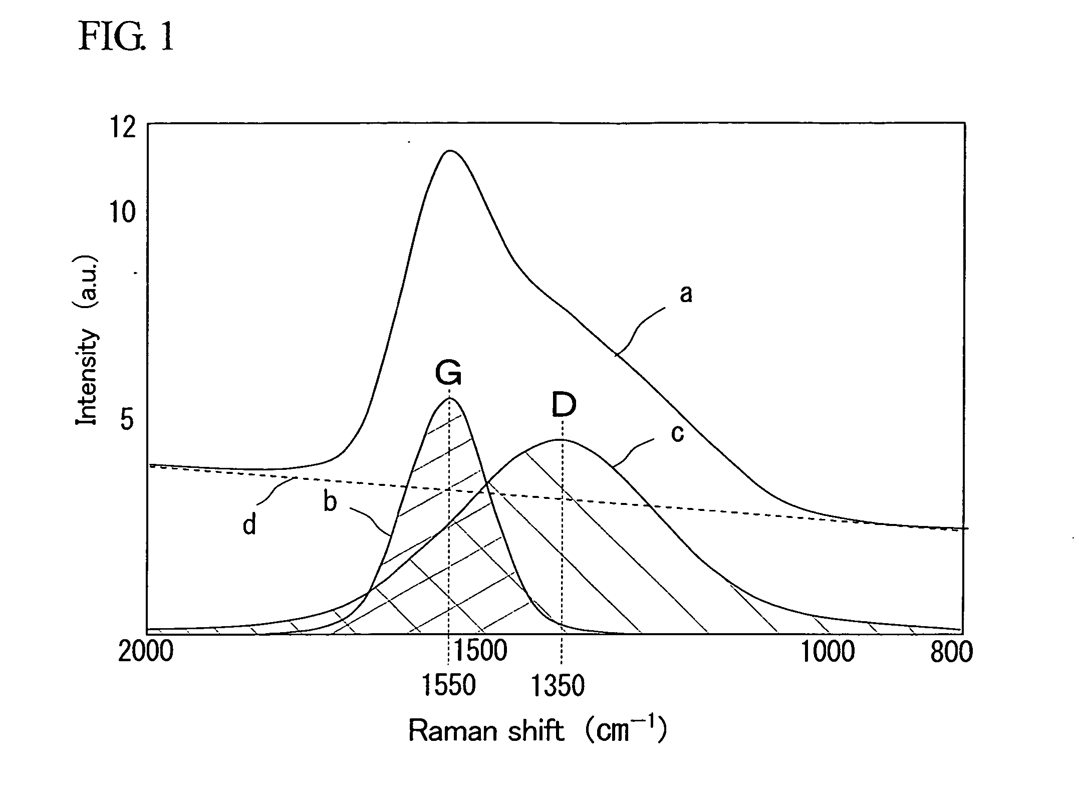
[0033] Block test piece: As a substrate on which an amorphous carbon film is formed, stainless steel (SUS440C; JIS) 15.7×10.0×6.3 mm in dimensions having as its surface roughness a center line average roughness of Ra 0.05 μm was prepared. As shown in FIG. 1, an amorphous carbon film was formed on the surface of the substrate (on the 15.7×6.3 mm side) by the plasma PVD method while adjusting the carrier gas flow rate, the applied plasma voltage, the temperature, and the like in a manner such that the D (line c in FIG. 1) to G (line b in FIG. 1) band integrated intensity ratio in the Raman spectrum (ratio of a hatched area below line c to a hatched area below line b) became 1.58 (see tables 1 and 2). In addition, the total intensity of scattered light relative to incident light shown as ...

example 2

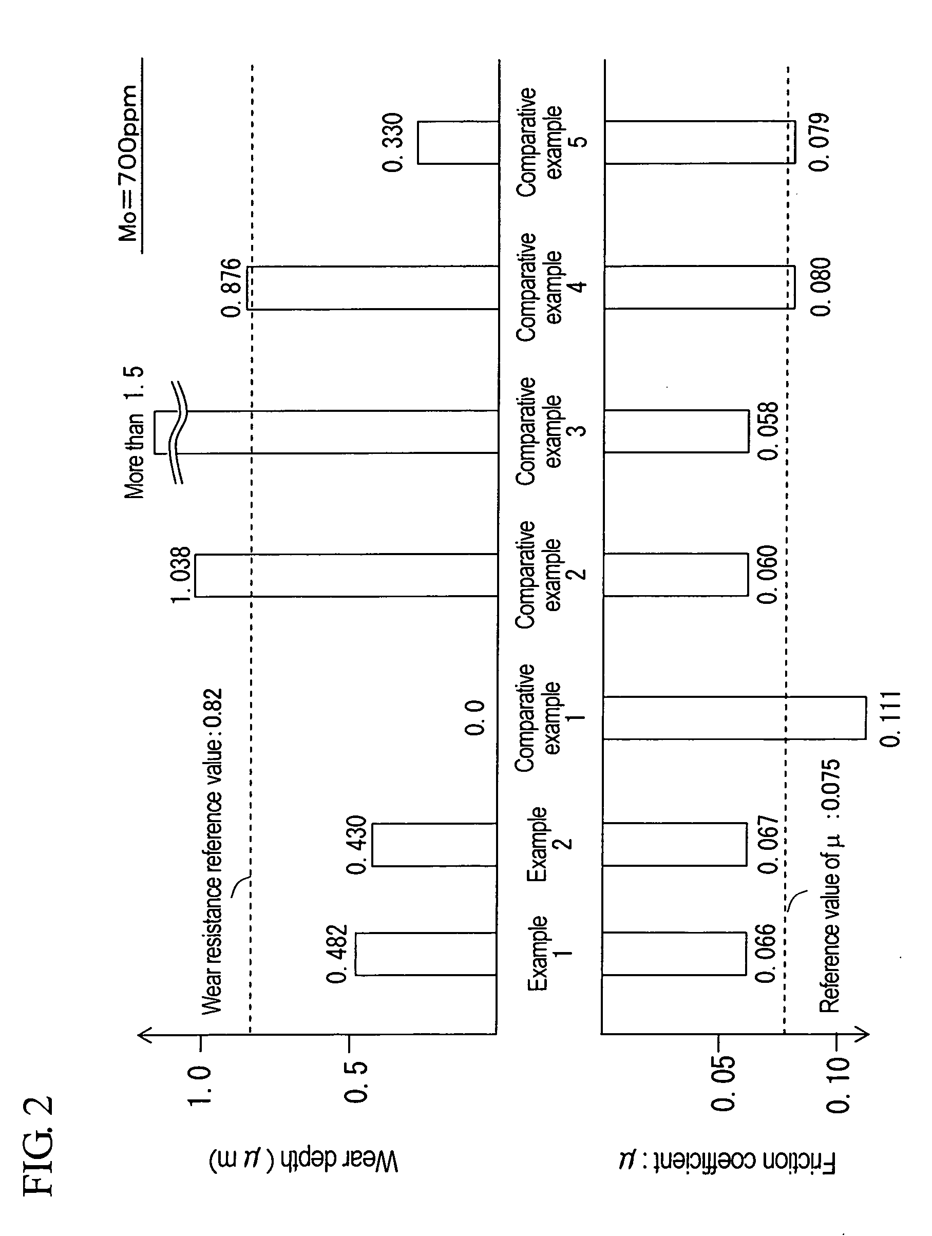
[0037] After a substrate was produced as with the case of Example 1, a block test piece was produced in a manner such that an amorphous carbon film was formed on the surface of the substrate by the plasma CVD method while adjusting the concentration and the flow rate of hydrocarbon gas, the applied plasma voltage, the temperature of the substrate, and the like, resulting in a D to G band integrated intensity ratio in the Raman spectrum of 1.79 (see tables 1 and 2).

[0038] In addition, a ring test piece and lubricating oil were provided as with the case of Example 1. As with the case of Example 1, a frictional wear test was conducted so as to determine the friction coefficient and the wear volume. The results are shown in table 2 and FIG. 2.

examples 3 to 6

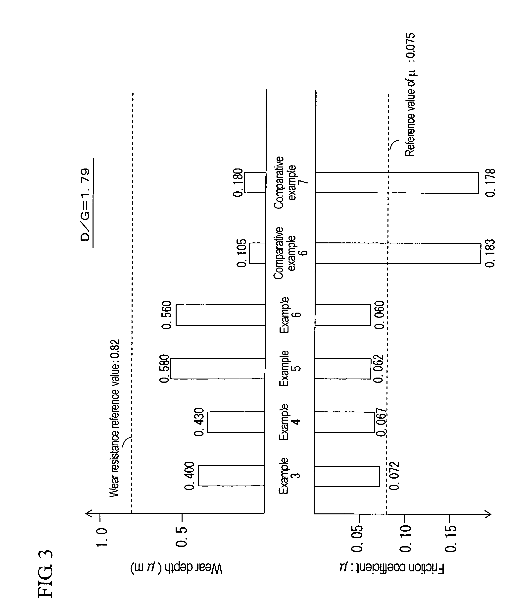
[0053] A block test piece and a ring test piece were provided as with the case of Example 2, and lubricating oils to be fed between them were also provided. Examples 3 to 6 were different from Example 2 in that the lubricating oils used in Examples 3 to 6 contained Mo-DTC in a manner such that the molybdenum contents in the lubricating oils became 400 ppm, 700 ppm, 800 ppm, and 900 ppm, respectively. Also, as with the case of Example 2, a frictional wear test was conducted so as to determine the friction coefficient and the wear volume in Examples 3 to 6. In addition, Example 4 was conducted under the same conditions as in Example 2. The results are shown in table 3 and FIG. 3.


PUM

PropertyMeasurementUnit
Fractionaaaaaaaaaa
Fractionaaaaaaaaaa
Fractionaaaaaaaaaa

Abstract

According to the present invention, a sliding structure whereby wear resistance of a pair of sliding members that are able to slide relative to each other is improved and the friction coefficient can be reduced is provided. The sliding structure in which a lubricating oil is fed between sliding faces of a pair of sliding members that are able to slide relative to each other such that at least one of the members is allowed to slide is provided. The sliding structure is characterized in that: an amorphous carbon film is formed on the sliding face of at least one sliding member so as to result in a D to G band integrated intensity ratio in the Raman spectrum of between 1.5 and 2.0; and the lubricating oil existing between the sliding faces contains a compound comprising at least molybdenum and sulfur so as to result in a molybdenum content of not less than 400 ppm relative to the lubricating oil.

Description

BACKGROUND OF THE INVENTION [0001] 1. Field of the Invention [0002] The present invention relates to a sliding structure, in which a lubricating oil is fed between sliding faces of a pair of sliding members that are able to slide relative to each other such that at least one of the sliding members is allowed to slide. Particularly, the present invention relates to a sliding structure in which wear resistance and low-friction characteristics of the sliding faces of such members are improved. [0003] 2. Background Art [0004] Heretofore, sliding members have been used in various types of devices such as engines and transmissions for automobiles. There have been various forms of ongoing research and development aimed at decreasing sliding resistance between sliding members for energy loss reduction so as to meet the future fuel efficiency requirements for the purpose of global environmental preservation. For instance, one example of such research and development relates to a technology o...

Claims


Application Information

Patent Timeline
IPC IPC(8): C10M135/18
CPCC10M125/22C10M135/18C10M137/10C10M141/08C10M141/10C10M2201/066C10M2219/068C10M2223/045C10N2210/06C23C14/0605C23C16/26F16C33/10C10N2010/12
Inventor NAKAGAWA, IKUOOGAWA, MASAAKIFUWA, YOSHIOOZAKI, YOSHINORI
Owner TOYOTA JIDOSHA KK
Why Eureka
Try Eureka