Submount substrate for mounting light emitting device and method of fabricating the same

a technology substrates, which is applied in the direction of semiconductor/solid-state device manufacturing, semiconductor devices, electrical devices, etc., can solve the problems of failure of light emitting devices, inability to reduce manufacturing costs, and worse problems, so as to reduce the process of diffusion masks and reduce manufacturing costs

Inactive Publication Date: 2007-04-12
LG ELECTRONICS INC
View PDF2 Cites 18 Cited by
  • Summary
  • Abstract
  • Description
  • Claims
  • Application Information

AI Technical Summary

Benefits of technology

[0027] The present invention is conceived to solve the aforementioned problem. Accordingly, an object of the present invention is to provide a submount substrate for mounting a light emitting device and a method of fabricating the same, wherein the submount substrate for mounting the light emitting device in which a Zener diode device is integrated can be fabricated by means of a silicon bulk micromachining process without using a diffusion mask, thereby reducing processes related to the diffusion mask and thus reducing manufacturing costs.

Problems solved by technology

In the meantime, if static electricity or surge voltage is produced in this type of light emitting device, an excessive electric charge flows into the semiconductor layers and finally causes failure of the light emitting device.
This problem becomes worse in a case where the devices are fabricated on the top of a dielectric substrate.
Accordingly, there is a problem in that manufacturing costs can not be reduced due to increased the number of manufacturing processes.

Method used


Image

  • Submount substrate for mounting light emitting device and method of fabricating the same
  • Submount substrate for mounting light emitting device and method of fabricating the same
  • Submount substrate for mounting light emitting device and method of fabricating the same

Examples


first embodiment

[0043]FIGS. 4a to 4g are cross-sectional views illustrating a method of fabricating a submount substrate for mounting a light emitting device according to the present invention, and show a process of fabricating the submount substrate for mounting the light emitting device in which a Zener diode capable of protecting a light emitting device from a surge voltage or static electricity is integrated, using a silicon bulk micromachining process.

[0044] Referring to FIG. 4a, a substrate (300) doped with first polar impurities is first prepared.

[0045] Preferably, the substrate (300) is a silicon substrate.

[0046] Then, on the top and bottom surfaces of the substrate (300) are injected and diffused second impurities having the polarity different from that of the first polar impurities to form first and second diffusion layers (310. 311). (see FIG. 4b)

[0047] At this time, the second polar impurities can be injected and diffused into the top and bottom surfaces of the substrate (310) withou...

second embodiment

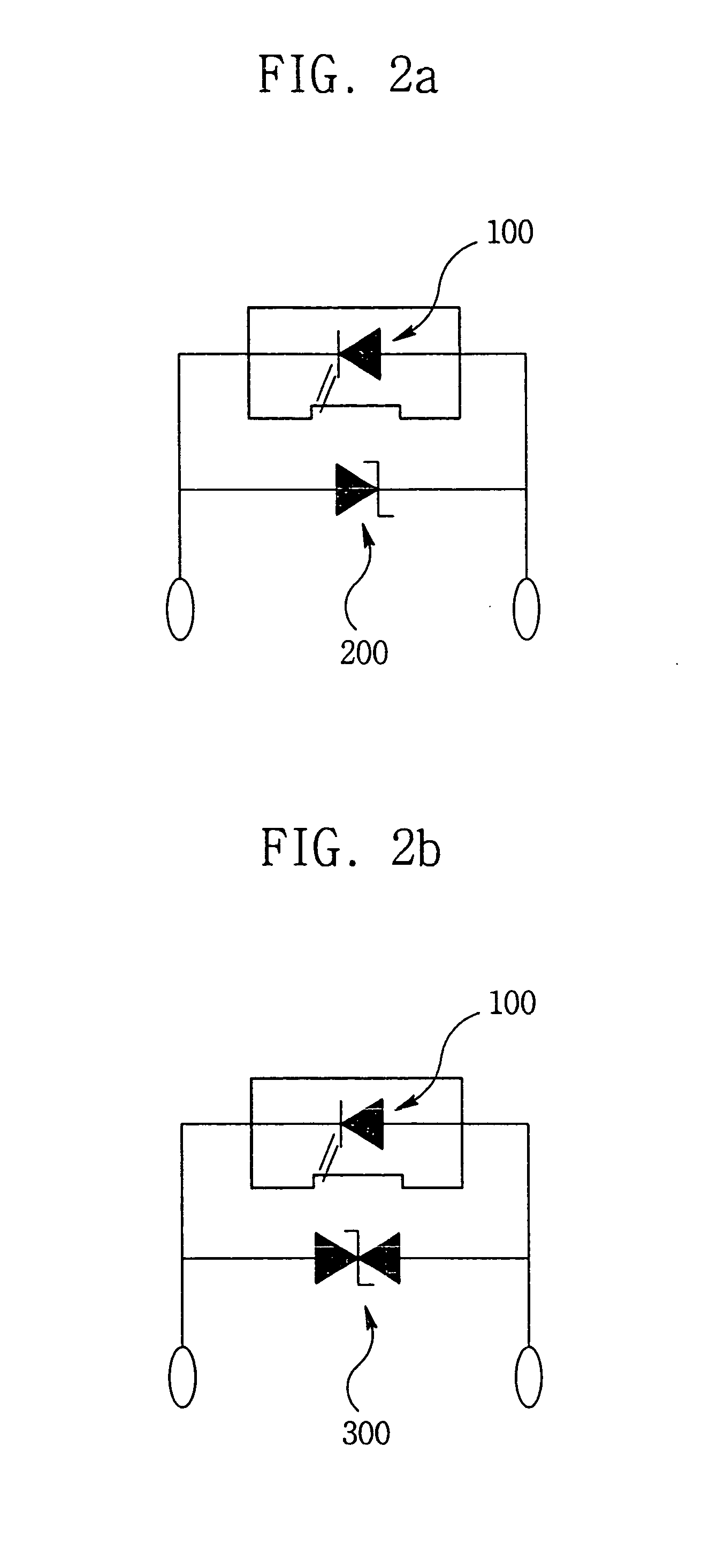
[0068]FIGS. 7a to 7i are cross-sectional views illustrating a method of fabricating a submount substrate for mounting a light emitting device in which a Zener diode having a bi-directional threshold voltage characteristic is integrated according to the present invention. Herein, a PNP (or NPN) Zener diode is used as the Zener diode having the bidirectional threshold voltage characteristic.

[0069] First, a substrate (300) doped with first polar impurities is prepared. (see FIG. 7a)

[0070] Preferably, the substrate (300) is a silicon substrate.

[0071] Then, on the top and bottom surfaces of the substrate (300) are injected and diffused second impurities having the polarity different from that of the first polar impurities to form first and second diffusion layers (310. 320). (see FIG. 7b)

[0072] Successively, mask layers (510. 520) are formed on the top and bottom surfaces of the substrate (300), respectively. Some parts of the mask layer (510) formed on the top surface of the substrat...


PUM


Abstract

A submount substrate for mounting a light emitting device and a method of fabricating the same, wherein since a submount substrate for mouthing a light emitting device in which a Zener diode device is integrated can be fabricated by means of a silicon bulk micromachining process without using a diffusion mask, some steps of processes related to the diffusion mask can be eliminated to reduce the manufacturing costs, and wherein since a light emitting device can be flip-chip bonded directly to a submount substrate for a light emitting device in which a Zener diode device is integrated, a process of packaging the light emitting device and the voltage regulator device can be simplified.

Description

CROSS-REFERENCE TO RELATED APPLICATIONS [0001] This application is a Divisional Application of prior U.S. patent application Ser. No. 11 / 174,640 filed Jul. 6, 2005, which claims priority under 35 U.S.C. §119 to Korean Application No. 10-2004-0053640 filed on Jul. 9, 2004, whose entire disclosure is hereby incorporated by reference.BACKGROUND [0002] 1. Field of the Invention [0003] The present invention relates to a submount substrate for mounting a light emitting device in which a Zener diode used as a voltage regulator device is integrated, and a method of fabricating the same. More particularly, the present invention relates to a submount substrate for mounting a light emitting device in which a PN Zener diode or a Zener diode having a bi-directional threshold voltage characteristic is integrated using a silicon bulk micromachining process, and a method of fabricating the same. [0004] 2. Description of the Related Art [0005] In general, a light emitting device such as a light emit...

Claims


Application Information

Patent Timeline
Patent Type & Authority Applications(United States)
IPC IPC(8): H01L31/00H01L33/32H01L33/60H01L33/62
CPCH01L25/167H01L2924/3011Y10S438/942H01L2224/14H01L2924/0002H01L2924/00
Inventor KIM, GEUN HOPARK, CHIL KEUN
Owner LG ELECTRONICS INC
Why Eureka
Try Eureka