Filter and composite filter, filter assembly, integrated circuit chip and electronic device which contain same, and frequency characteristic changing method therefor

a filter and composite technology, applied in the direction of impedence networks, electrical devices, transmission, etc., can solve the problems of difficult to arbitrarily change the bandwidth, difficult to provide a mechanism for varying the center frequency and bandwidth, and the technique described in reference b>1/b> is incapable of adjusting the frequency characteristics by a movable mechanism, etc., to reduce the size of the device, improve reliability, and cost-down

Active Publication Date: 2007-04-12
NEC CORP
View PDF5 Cites 37 Cited by
  • Summary
  • Abstract
  • Description
  • Claims
  • Application Information

AI Technical Summary

Benefits of technology

[0008] It is an object of the present invention to provide a small-sized and high performance filter, using the MEMS technologies, which is capable of modifying shifts and variations of the general frequency characteristics to respective desired design values, respectively, by a movable mechanism integrated by the MEMS technologies and mechanically controllable with electric signals, and is capable of changing the frequency characteristics to support a variety of standards, which have different frequency bands and center frequencies, by varying the general frequency characteristics of the filter individually to desired target values in an electrically controllable form, as is required for a software radio, a frequency characteristic changing method therefor, and a small-sized and reliable electronic device which is equipped with the foregoing filter.
[0039] Thus, the present invention arranges the input and output electrodes and the acoustic wave resonator adjacent to them on the substrate, and enables the center frequency of the resonator, the coupling coefficient between the resonance modes, and the external Q-value to be individually changed by the electromechanical transducer, thus making it possible to arbitrarily change the frequency characteristics of the filter, so that the present invention can provide a filter which satisfies characteristics required by telecommunication devices such as a software radio, and electronic devices, and a method of changing its frequency characteristics. Also, according to the present invention, it is possible to appropriately correct the frequency characteristics for shifts caused by manufacturing-induced variations.
[0040] Also, when the filter and associated peripheral circuit are integrated on the same substrate, it is possible to reduce the size of the device and improve the reliability. Also, in an electronic device such as a telecommunication device which contains the filter according to the present invention, a cost-down can be achieved for the product, in addition to the ability to reduce the size of the device and improve the reliability.

Problems solved by technology

However, with currently used surface acoustic wave filters, dielectric filters, or laminated ceramic filters, or SAW filters, it is extremely difficult to provide a mechanism for varying the center frequency and bandwidth, as desired in the software radio.
Also, a magnetostatic wave filter is known as a device which is a filter that is available in GHz bands and has a variable center frequency, but even with this device, it is difficult to arbitrarily change the bandwidth.
Therefore, the technique described in Reference 1 is incapable of adjusting the frequency characteristics by a movable mechanism which is instructed in software and is mechanically controllable with electric signals.
However, in filters using the conventional MEMS technologies, there has not so far been proposed any filter which can adjust shifts from and variations in design values with respect to general frequency characteristics of a filter, i.e., all characteristics such as the center frequency, bandwidth, rejection characteristic, insertion loss, and phase characteristic.
Also, even in an MEMS filter which can adjust shifts and variations in part of the frequency characteristics by a movable mechanism fabricated by such MEMS technologies and mechanically controllable with electric signals, there has not so far been contemplated any system which can change the frequency characteristics to support a variety of standards having different frequency bands and center frequencies by varying the frequency characteristics of the filter in an electrically controllable form, as is required by the software radio.

Method used


Image

  • Filter and composite filter, filter assembly, integrated circuit chip and electronic device which contain same, and frequency characteristic changing method therefor
  • Filter and composite filter, filter assembly, integrated circuit chip and electronic device which contain same, and frequency characteristic changing method therefor
  • Filter and composite filter, filter assembly, integrated circuit chip and electronic device which contain same, and frequency characteristic changing method therefor

Examples


Embodiment Construction

[0135] Next, examples of the present invention will be described in detail with reference to the accompanying drawings.

[0136]FIG. 4 are diagrams illustrating a first example of the present invention, wherein FIG. 4A is a top plan view which additionally depicts the configuration of peripheral circuits; FIG. 4B is a front view, FIG. 4C is a side view, and FIG. 4D is a schematic diagram for describing the operation of an acoustic wave resonator.

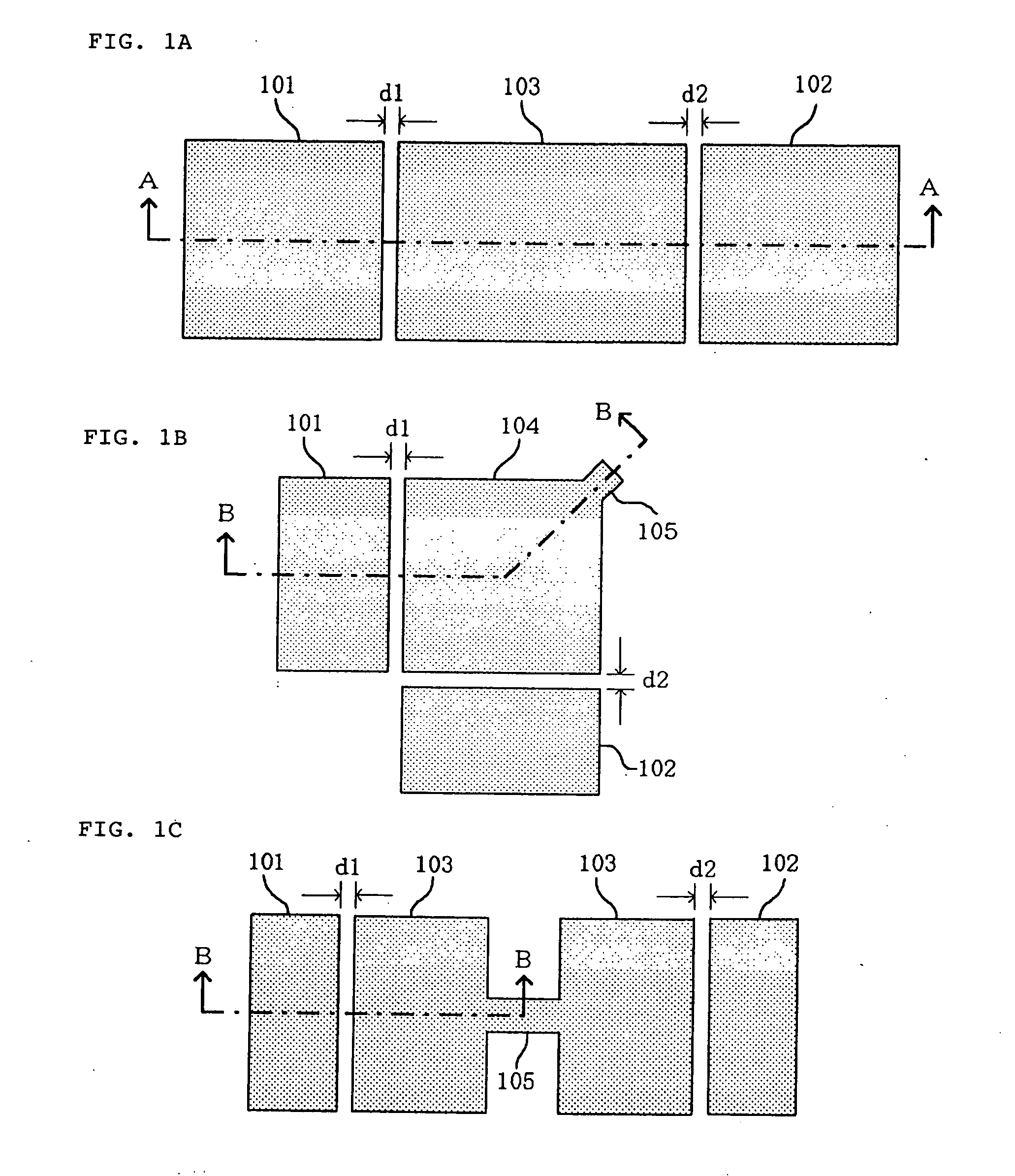
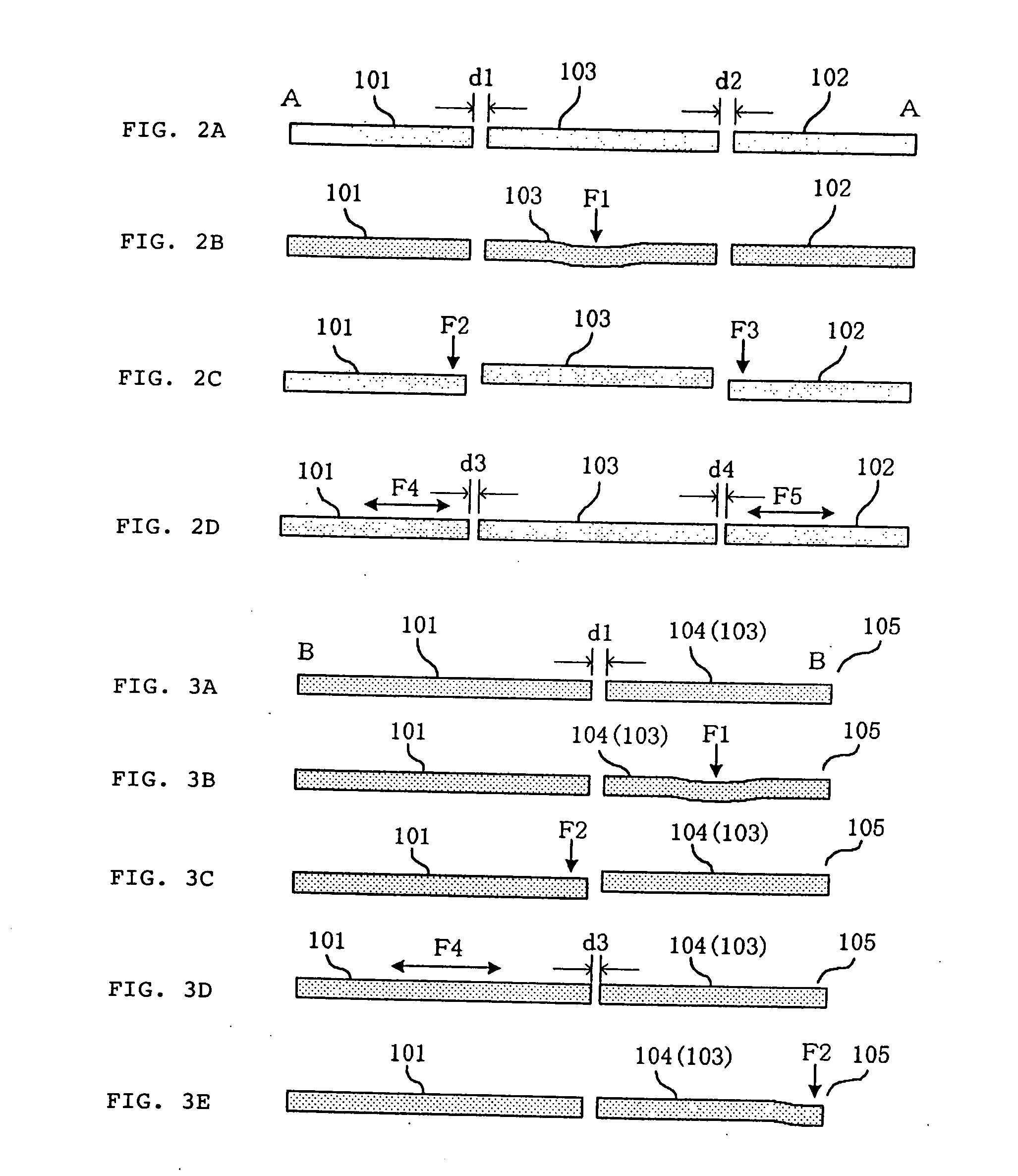
[0137] As illustrated in FIG. 4, the filter of this example mainly comprises input electrode 2 and output electrode 3 on substrate 1, and dual-mode acoustic wave resonator 7a disposed therebetween across narrow voids 4, 5 and having the shape of a square except for resonance mode inter-coupler 6, when viewed from above. The vertical and horizontal widths of this dual-mode acoustic wave resonator 7a are chosen to match the length of one waveform when a designed resonance frequency is realized, in consideration of the speed of acoustic waves th...


PUM


Abstract

A dual-mode acoustic wave resonator (7a) having a resonance mode inter-coupler (6) is disposed across narrow voids (4, 5) from an input electrode (2) and an output electrode (3). They are supported for vibrations on a substrate by conductive posts (27, 28, 29) and a power supply pad (3). Opposing electrodes (10, 11, 21, 23) are formed below the input and output electrodes (2, 3), resonator (7a), and resonance mode inter-coupler (6) across narrow gaps. As a voltage of a power supply (25) is changed, a distortion of the resonator (7a) changes due to an electrostatic force, causing a change in the center resonance frequency. As voltages of power supplies (16, 17) are changed, distortions of the input and output electrodes (2, 3) change to cause a change in the opposing areas of end faces of the input and output electrodes to the resonator (7a). This causes a change in the situation of exchanging energy between the input and output electrodes and the resonator (7a) to change the external Q-value. As the voltage of the power supply (25) is changed, a distortion of the inter-coupler (6) changes to cause a change in the coupling coefficient between the resonance modes.

Description

TECHNICAL FIELD [0001] The present invention relates to filters for use in telecommunication circuits, and a frequency characteristic changing method therefor, and more specifically, to a filter fabricated using an acoustic wave resonator with the employment of micro-electromechanical system (MEMS) technologies, a frequency characteristic changing method therefor, as well as electronic devices such as a mobile telephone, a telecommunication device and the like which have the filter mounted therein. BACKGROUND ART [0002] At present, in radio telecommunication systems represented by wireless LAN, mobile telephone systems, and so on, modulation / demodulation schemes, assigned frequencies, and the like are different depending on differences in system and country. Under such a situation, developments are now actively under way for a software radio which can support a variety of systems with one type of radio. In this software radio, it is desired that not only a modulation scheme but also...

Claims


Application Information

Patent Timeline
Patent Type & Authority Applications(United States)
IPC IPC(8): H04B1/18H04B1/16H03H9/54H03H3/04H04B1/00
CPCH03H9/542H04B1/006
Inventor HATTORI, WATARU
Owner NEC CORP
Why Eureka
Try Eureka