Deposition device

a technology of evaporation source and evaporation material, which is applied in the direction of energy-based chemical/physical/physico-chemical processes, nuclear engineering, transportation and packaging, etc., can solve the problems of limited evaporation material with which an evaporation source can be filled, affecting the quality of evaporation materials, and limiting the size of evaporation sources, so as to achieve the effect of improving the throughpu

Inactive Publication Date: 2007-04-19
SEMICON ENERGY LAB CO LTD
View PDF23 Cites 50 Cited by
  • Summary
  • Abstract
  • Description
  • Claims
  • Application Information

AI Technical Summary

Benefits of technology

[0020] In the present invention, the term “a material supply portion intermittently supplies an evaporation material to the evaporation source” means that the supply of the evaporation material is arbitrarily stopped and restarted according to the design of the thin film pattern. In other words, the material supply portion selectively supplies the evaporation material to the evaporation source. For example, the evaporation material is selectively discharged from the material supply portion to a hot plate included in the evaporation source. Among this selective discharging, the not plate may not be cooled down and re-heated up, and may be remained at a constant temperature. According to this, the stopping and the restarting of the depositing becomes quick.
[0021] In accordance with the present invention, even in a case of using a display panel having a large screen, deposition can be performed uniformly and continuously. Further, an evaporation material is not needed to be supplied to an evaporation source every time the evaporation material runs out; therefore, throughput can be improved.

Problems solved by technology

However, the amount of evaporation materials with which an evaporation source can be filled is limited in depositing an EL layer.
Therefore, continuous treatment of a plurality of substrates having a large size becomes increasingly difficult.
That is, the large amount of evaporation materials is needed to evaporate the EL layer continuously to a glass substrate having a large size; however, there is a problem that a crucible as an evaporation source has a limitation on a size and the evaporation source can not be filled with the sufficient amount of evaporation materials.
Therefore, a problem occurs, in which evaporation operation is needed to be interrupted to refill the evaporation source with the evaporation material in each time.
In evaporation, a predetermined time is needed to stabilize a temperature of the evaporation source, and a material that evaporates in the meantime becomes waste.
Accordingly, a yield of the material is lowered, and degradation of throughput is caused.

Method used


Image

  • Deposition device
  • Deposition device
  • Deposition device

Examples


embodiment mode 1

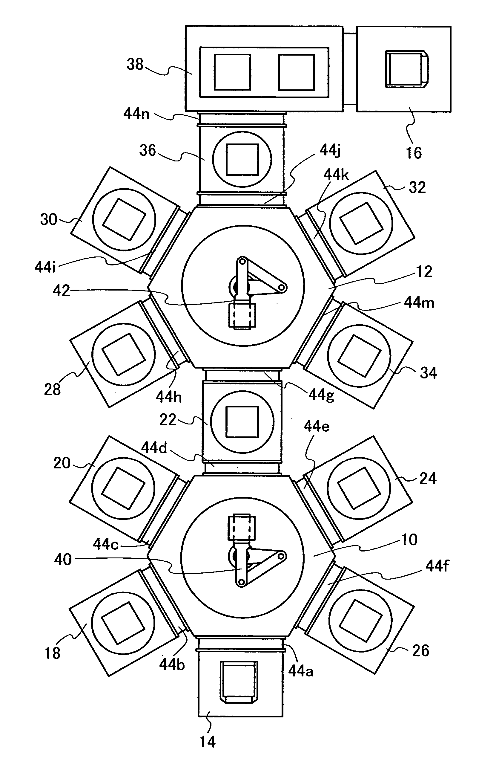
[0061] In this embodiment mode, a structure of a deposition device having a deposition treatment chamber that includes an evaporation source provided with a means for supplying a material for evaporation to a heating portion, will be explained with reference to FIG. 1 and FIG. 2.

[0062]FIG. 1 shows a structure of a deposition device for forming an EL layer over a substrate. The EL layer is a main part of an EL element utilizing EL. A diode-type EL element has a structure in which an EL layer is interposed between a pair of electrodes. In this element, the EL layer is formed of one layer or a plurality of layers each having a different function. In this case, the EL layer can be formed by combining layers each having a different function, which are also referred to as a hole injecting and transporting layer, a light emitting layer, an electron injecting and transporting layer, and the like. It is to be noted that the EL layer indicates a layer containing a material that develops elec...

embodiment mode 2

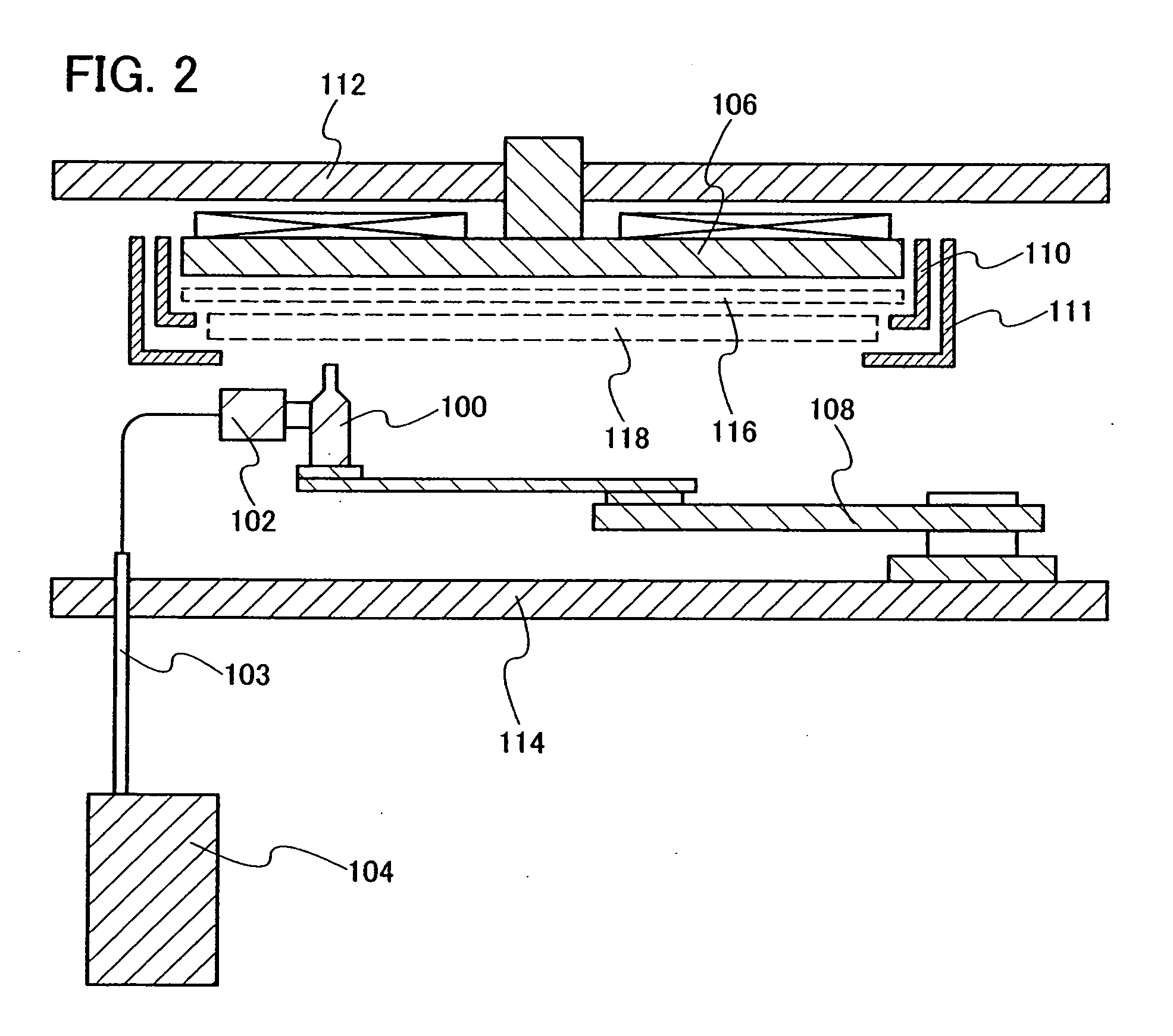
[0085] In this embodiment mode, a structure of a deposition treatment chamber in which an evaporation source is fixed and a substrate is moved to perform evaporation will be explained with reference to FIG. 3.

[0086]FIG. 3 shows an internal structure of a deposition treatment chamber. The deposition treatment chamber is kept under a reduced pressure. In the deposition treatment chamber, an evaporation source, a jig for fixing a substrate, and the like are arranged to be interposed between a top plate 112 and a bottom plate 114.

[0087] An evaporation source 100, a material supply portion 102, a material supply tube 103, and a material supply source 104, which are provided in the deposition treatment chamber, have the same structure as that of Embodiment Mode 1. In a case of depositing a plurality of layers each having a different composition or in a case of co-evaporating different materials, a plurality of the evaporation sources can be provided. The evaporation source 100 is mounte...

embodiment mode 3

[0091] In this embodiment mode, a structure of a deposition treatment chamber in which both an evaporation source and a substrate are moved to perform evaporation will be explained with reference to FIG. 9.

[0092] In an internal structure of a treatment chamber shown in FIG. 9, an evaporation source 100 provided in a deposition treatment chamber 174 has the same structure as that of Embodiment Mode 1. One or a plurality of the evaporation sources 100 can be provided. The evaporation source 100 is provided over a movement mechanism 176 including a pulley or a gear so as to be capable of moving up and down by a second guide rail 178. Transfer speed of a substrate transferring mechanism 180 that moves over a first guide rail 182 and moving speed of the evaporation source 100 that moves up and down by the second guide rail 178 are appropriately adjusted, whereby a deposition rate and film thickness distribution can be adjusted.

[0093] In addition, a heater 184 may be provided over a sur...


PUM

PropertyMeasurementUnit
distanceaaaaaaaaaa
sizeaaaaaaaaaa
sizeaaaaaaaaaa

Abstract

It is an object of the present invention to provide a deposition device that can selectively form a thin film without using a shadow mask with respect to a substrate having a large size. In the deposition device, an evaporation source is provided with a cylinder cell, a heater for heating a lower part of the cylinder cell, and a heater for heating an upper part of the cylinder cell. A hot plate can control a temperature by a heater provided inside thereof. The hot plate heats an evaporation material supplied into the cylinder cell from a material supply portion that is connected to the cylinder cell, and vaporizes the evaporation material by evaporation or sublimation. A rotating mechanism for rotating the hot plate in the cylinder cell may be provided to achieve uniformity of a temperature. A heater for heating the material supply potion may be provided to raise a temperature of the evaporation material supplied into the cylinder cell. By such an evaporation source, deposition can be uniformly and continuously performed with respect to a substrate having a large size.

Description

BACKGROUND OF THE INVENTION [0001] 1. Field of the Invention [0002] The present invention relates to a deposition device for forming a film by evaporation. In particular, the present invention relates to a deposition device that can be used for manufacturing a display device utilizing electroluminescence. [0003] 2. Description of the Related Art [0004] As a typical method for forming a thin film, an evaporation method is known. An evaporation method is known as a technique in which a material to be evaporated in vacuums is heated and vaporized, and then, the material is attached to a surface of the object as a thin film. An evaporation method is used in various fields as a technique for forming a thin film. For example, the evaporation method is applied to manufacture an electroluminescence element (hereinafter, also referred to as an “EL element”) using an organic material. There are many structures of a device for evaporating a thin film. As a device used for manufacturing an orga...

Claims


Application Information

Patent Timeline
Patent Type & Authority Applications(United States)
IPC IPC(8): B01J19/08C23C16/00
CPCC23C14/04C23C14/12H01L51/56C23C14/246C23C14/243H10K71/00H01L21/20
Inventor ARAI, YASUYUKI
Owner SEMICON ENERGY LAB CO LTD
Why Eureka
Try Eureka