
Process for preparing copolymers and blend compositions containing the same

Inactive Publication Date: 2007-04-19
DOW GLOBAL TECH LLC
View PDF87 Cites 16 Cited by
  • Summary
  • Abstract
  • Description
  • Claims
  • Application Information

AI Technical Summary

Benefits of technology

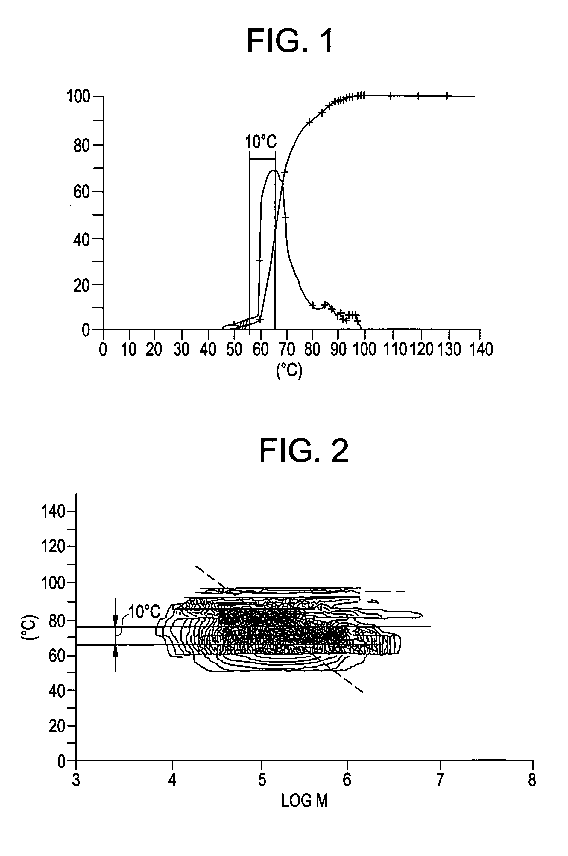
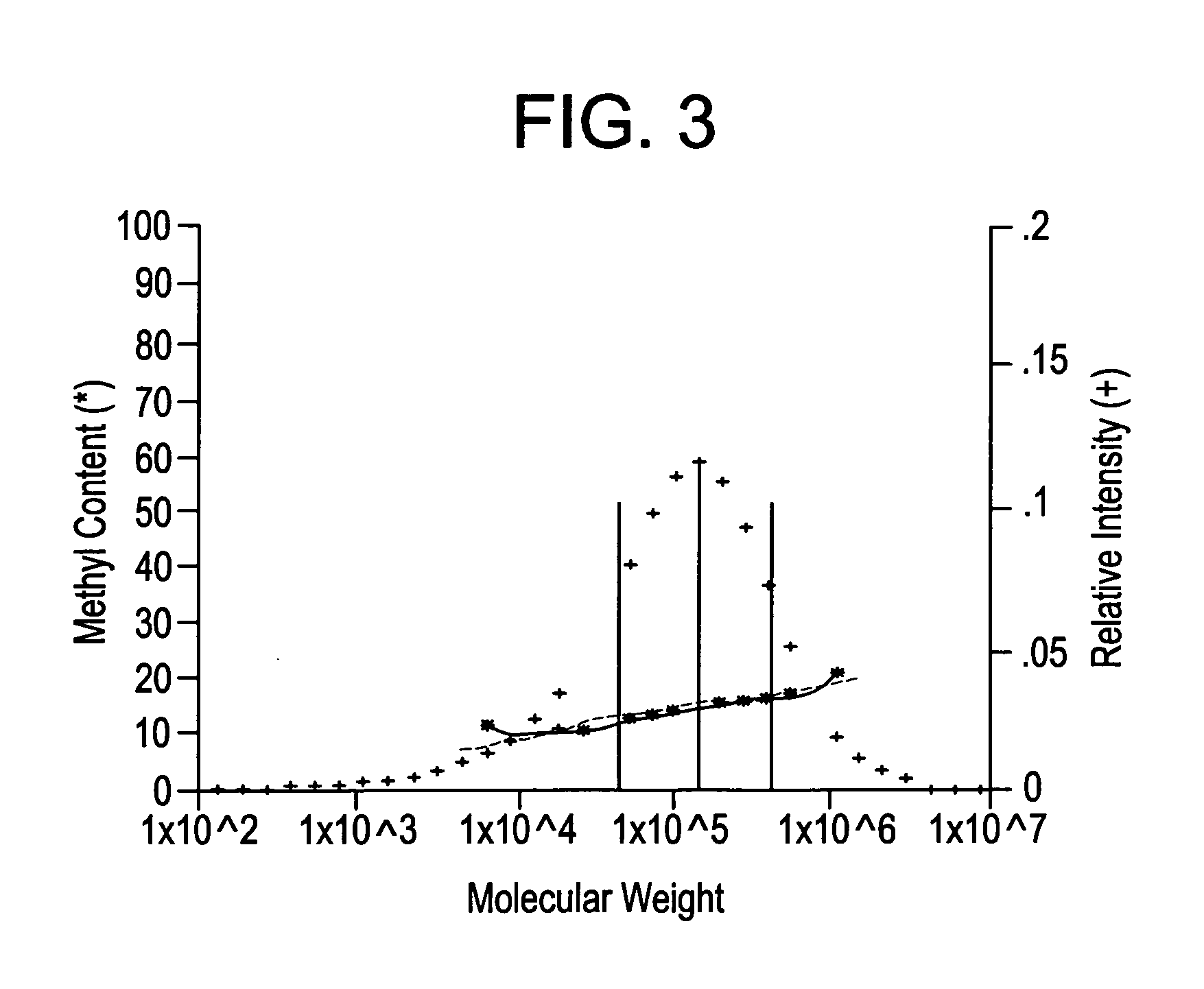
[0032] Accordingly, it is one object of the present invention to provide a novel ethylene copolymer which not only contains substantially no impurities such as a wax, a gel, but also exhibits a comonomer content distribution in which the lower the molecular weight of a fraction of said copolymer the lower the comonomer content and the higher the molecular weight of a fraction of said copolymer the higher the comonomer content.

Problems solved by technology

However attempts to vary the molecular structure of a polymer to cause an improvement in one such property often results in a loss of performance in another.
For instance polymers exhibiting high stiffness and heat resistance should have high crystallinity and low comonomer content, however this can cause a loss of toughness, ESCR, low optical properties and poor heat seal performance.
However broad molecular weight distribution, especially at low polymer molecular weight, often causes wax buildup on the die, smoke generation on the extruder, and taste and odor problems in the resulting fabricated articles.
Thus, such conventional ethylene copolymers have a comonomer content distribution which is completely contrary to the above-mentioned desired comonomer content distribution.
Therefore, such conventional ethylene copolymers are at a disadvantage with respect to desirable properties, such as improved impact strength and ESCR.
The presence of the low molecular weight material can disadvantageously lead to wax formation.
On the other hand, the high molecular weight material can disadvantageously lead to gel formation.
This can lead to the component polymers undergoing phase separation such that the dispersion of the component polymers becomes non-uniform, and thus not only does the ethylene copolymer become non-uniform in properties but also gel formation occurs.
On the other hand, however, ethylene copolymers produced using a metallocene catalyst are still unsatisfactory with respect to desired improvements in impact resistance and ESCR properties of products of such copolymers.
Therefore, when two different types of copolymers, namely a low molecular weight copolymer and a high molecular weight copolymer which are extremely different in molecular weight from each other, are produced using different metallocene catalysts, the respective amounts of copolymer chains having common molecular weights is very small in the two different copolymers, so that the compatibility between these two different copolymers is very poor.

Method used


Image

  • Process for preparing copolymers and blend compositions containing the same
  • Process for preparing copolymers and blend compositions containing the same
  • Process for preparing copolymers and blend compositions containing the same

Examples


example 1

[0459] 20 g of silica SP-9-10046 (manufactured and sold by Grace GmbH, Germany), which had been treated at 250° C. for 2 hours under vacuum, was slurried in 250 ml of toluene. To the resultant slurry was added a solution of 20 ml (0.11 mol) of triethylaluminum in 100 ml of toluene. The resultant mixture was stirred for 2 hours, filtered, washed with two 100 ml portions of fresh toluene and dried under vacuum. The resultant 22 g of dried mixture was slurried in 300 ml of toluene and heated to 70° C. to thereby obtain a slurry. To this slurry was added a solution of 1.25 g (1.77 mmol) of triethylammonium tris(pentafluorophenyl)(4-hydroxyphenyl)borate in 200 ml of toluene which had been heated to and maintained at 70° C. for 30 minutes. Upon addition the heating was removed and the resultant mixture was stirred for 3 hours. After that, a 12.3 ml aliquot of a dark violet colored 0.0714M solution of titanium (N-1,1-dimethylethyl)dimethyl[1-(1,2,3,4,5,-eta)-2,3,4,5-tetramethyl-2,4-cyclope...

examples 2 and 3

[0462] 25 g of silica SP-9-10046 (manufactured and sold by Grace GmbH, Germany)having a water content of 3.5% by weight was added to 508 g of 10% methylalumoxane solution in toluene (manufactured and sold by Witco GmbH, Germany) while continuously stirring. The mixture was stirred for a further two hours and then the solvent was removed under reduced pressure at 20° C. to yield a free-flowing powder. The resulted free-flowing powder was then heated at 175° C. for two hours under vacuum. The resulting powder was re-slurried in 700 ml of toluene and the mixture was washed with two portions of fresh toluene at 100° C. The support was then dried under vacuum at 120° C. for 1 hour. 63.9 g of support was obtained having an aluminum content of 26.4% by weight.

[0463] To 60 gram of the support was added a 33.6 ml aliquot of a dark violet 0.0714 M solution of titanium (N-1,1-dimethylethyl)dimethyl[1-(1,2,3,4,5-eta)-2,3,4,5-tetramethyl-2,4-cyclopentadien-1-yl]silanaminato[(2-)N]-(eta 4-1,3-pe...

examples 4 to 6

[0465] Substantially the same procedures were used as in Examples 2 and 3 to produce the supported catalyst, except that a different MAO treated silica was used wherein the MAO was also immobilized on the silica, but using a different method.

[0466] Substantially the same polymerization procedures as in Example 1 were used, except that the polymerization temperatures and the flow rates of isopentane, 1-butene and hydrogen were changed as indicated in Table 1. The gradient and CFC 1 and CFC 2 data for Examples 4-6 are extrapolates, based on density, from the results of Example 1-3.

[0467] The results of the reactions are shown in Table 1.


PUM

PropertyMeasurementUnit
Temperatureaaaaaaaaaa
Fractionaaaaaaaaaa

Abstract

A process for the preparation of blends comprising an ethylene copolymer, which is prepared by polymerizing ethylene and at least one comonomer selected from (a) a compound represented by the formula H2C═CHR, wherein R is an alkyl group, an aryl group, or (b) a diene. The polymerization takes place in the presence of a solid catalyst system comprising a support, a transition metal compound and an activator capable of converting the transition metal compound into a catalytically active transition metal complex.

Description

REFERENCE TO PRIOR APPLICATIONS [0001] The present application is a divisional application of U.S. application Ser. No. 10 / 165,815, now allowed, which is a divisional of U.S. application Ser. No. 09 / 955,257, filed Sep. 18, 2001, now abandoned, which is a continuation of U.S application Ser. No. 09 / 180,788, filed Nov. 16, 1998, now abandoned, which is a national phase entry of International Application No. PCT / US97 / 08466, filed May 16, 1997, which claims priority to Japanese Patent Application No. H08-148392, filed May 17, 1996; each application is incorporated herein in its entirety by reference.FIELD OF INVENTION [0002] The present invention relates to an ethylene copolymer and a method for producing the same. More particularly, the present invention is concerned with an ethylene copolymer comprising a copolymer of ethylene with at least one comonomer selected from (a) the group comprising compounds represented by the formula H2C═CHR wherein R represents a C1-C20 linear, branched o...

Claims


Application Information

Patent Timeline
IPC IPC(8): C08L23/04C08F4/643B29C43/00B29C51/00C08F2/14C08F2/18C08F4/02C08F4/60C08F4/645C08F4/647C08F4/65C08F4/658C08F4/659C08F4/6592C08F10/00C08F210/02C08F210/16C08F297/08C08J5/00C08L23/06C08L23/08
CPCC08F4/65908C08F4/65912D01F6/46C08L2205/02C08L23/0815C08F4/65916C08F4/6592C08F10/00C08F210/16C08L23/04C08L23/06C08F2/14C08F2/001C08L2666/04C08F210/08C08F2500/12C08L2666/06C08F297/08
Inventor JACOBSEN, GRANT B.VAN DUN, JOZEF J.CHUM, PAK-WING S.MEISKE, LARRY A.MATSUSHITA, FUMIOMIYAMOTO, AKIRA
Owner DOW GLOBAL TECH LLC
Learn More