[0006] In accordance with the invention, the short-circuit current in the armature windings is regulated in a pulse-width-controlled manner. This is achieved in such a way for example that power breakers short the armature windings depending on the short-circuit duration by the closed-
loop control. The short-circuit current can be predetermined with the help of pulse-width modulation in such a way that the desired braking moment is obtained in an especially simple way. This allows not only keeping the braking moment virtually constant over the entire speed range, but also offers the possibility to
brake in an especially simple way with every torque smaller than the maximum one, because it may occur in a number of applications that damage will occur in the mechanism coupled via the
motor shaft of the synchronous machine by too strong braking. Any excessively strong rise of the short-circuit current can also be remedied elegantly with the closed-
loop control in accordance with the invention, which thus securely prevents any exceeding of the permissible short-circuit current and thus a demagnetization of permanent magnets. A further
advantage of the closed-
loop control in accordance with the invention is that after an occurred short-circuit braking, a short-circuit braking can be initiated directly thereafter and it is not necessary to wait for any cooling period, as is the case in
dynamic braking in accordance with the state of the art.
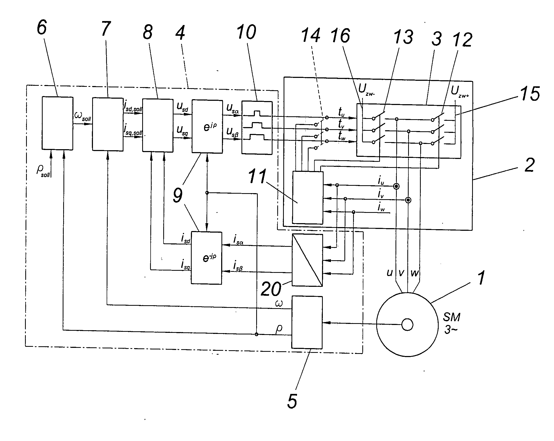
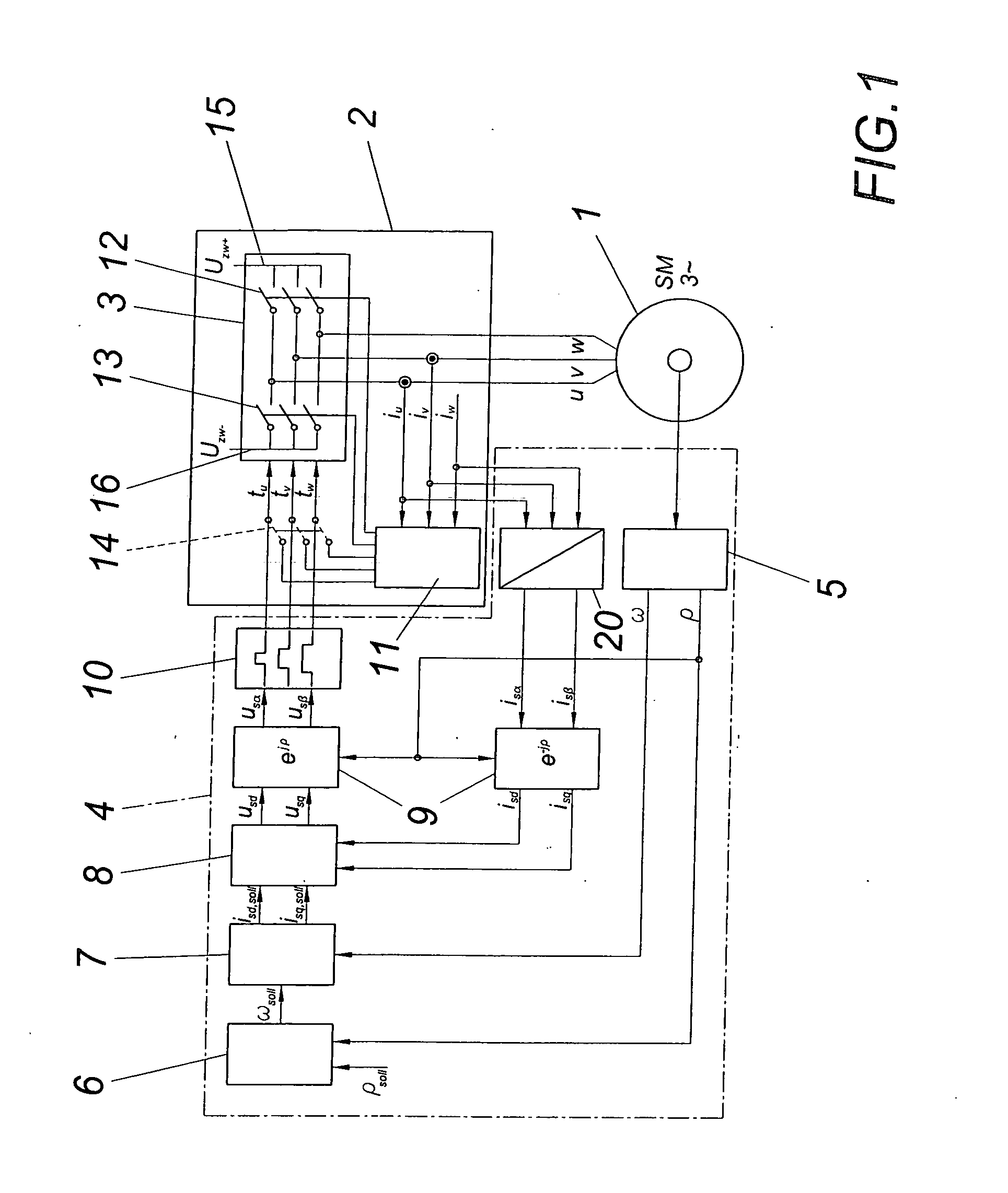
[0008] It is especially advantageous when the power breakers of two half-bridges of the converter which short the armature windings can be triggered in an alternating fashion by way of a closed-loop control device depending on the difference between the
setpoint value of the short-circuit current corresponding to the setpoint value of the braking moment and the actual value of the short-circuit current. As a result, both the half-bridge for positive half-
waves and the half-bridge for negative half-
waves of the power converter can be used as short-circuit elements, thus ensuring an improved thermal loading of the power breakers. The braking output is carried off according to this embodiment of the invention thus in an especially simple way via the power converter which can generally be highly loaded in a thermal respect, the armature windings and an optionally provided braking
resistor. As a result, the constructional complexity is minimized and only very few additional measures need to be provided for the braking operation of a synchronous machine in accordance with the invention.
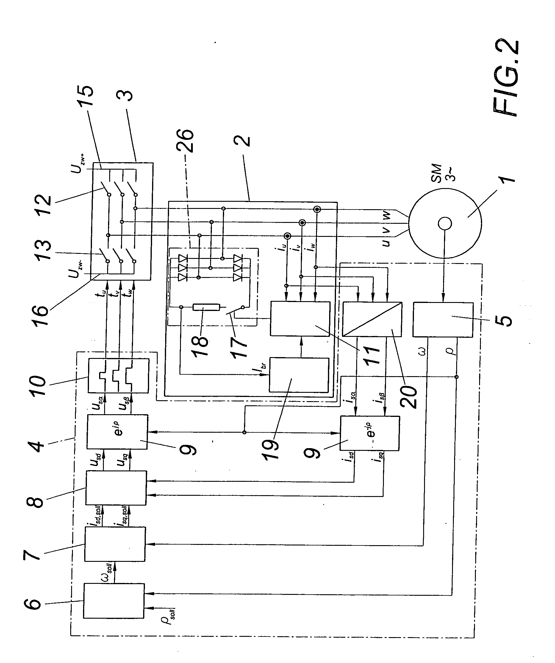
[0009] As an alternative to the above embodiment of a synchronous machine, a synchronous machine with a rotor and an armature winding, which can optionally be shorted via a braking resistor according to a further advantageous embodiment of the invention, can be characterized in that the armature windings are connected to a
rectifier circuit which can be shorted by way of a power breaker and that the power breaker can be triggered via a closed-loop control device depending on the difference between the setpoint value of the short-circuit current corresponding to the setpoint value of the braking moment and the actual value of the short-circuit current. According to this embodiment of a synchronous machine in accordance with the invention, the
short circuit for the armature windings is produced by way of a separate power
semiconductor circuit. The short-circuit current of the armature windings is rectified in the
rectifier circuit and the outputs for positive and negative half-waves are then shorted via a power breaker and optionally a braking resistor. A relevant
advantage of this synchronous machine in accordance with the invention is that the function of the braking device can be checked in an especially simple manner in a continuous or intermittent way. This is especially advantageous when high requirements are placed on the continuous availability of the braking device. A
control unit which is separately provided can ensure a short-circuit in the
rectifier circuit at short notice even during the operation of the synchronous machine and a separately provided monitoring device can ensure the
proper function of the braking device, e.g. by way of a current measurement in the shorted circuit. As was already mentioned, this functional test can also occur in operation of the
power inverter, as a result of which all components and functions of the braking device can be checked continually. As a result of providing two channels between the braking device and the power converter and of the continual checking capability of the braking device, an especially high safety class can be achieved.

