Apparatus and method for fabricating optical fiber preform.

a technology of optical fiber and apparatus, which is applied in the direction of metal-working holders, positioning apparatuses, supports, etc., can solve the problems of increasing the chances of capillary contamination, contamination or deformation of any kind of capillary has a severe negative impact on the attenuation of optical fiber, and the unwanted attenuation increase or other waveguide parameters of optical fiber, so as to avoid and inhibit leakage, the effect of being versatile and widely applicabl

Inactive Publication Date: 2007-05-03
STERLITE TECHNOLOGIES
View PDF7 Cites 6 Cited by
  • Summary
  • Abstract
  • Description
  • Claims
  • Application Information

AI Technical Summary

Benefits of technology

[0035] The main object of the present invention is to provide an improved rotary sealing mechanism for apparatus for fabricating optical fiber preform, wherein apparatus is suitable for a process of collapsing of capillary in the hollow soot porous body and particularly for a process comprising simultaneous sintering of the hollow soot porous body and collapsing of the capillary therein, and at the same time it neither suffers, at least, from majority of above described disadvantages, drawbacks and limitations of the prior art, nor from the main problem of leakage of rotary sealing mechanism, and hence the rotary sealing mechanism and the apparatus comprising the same and the methods employing such apparatus is highly satisfactory and highly economical in-addition to being easy to fabricate and easy to employ in the presently available apparatus for producing the optical fiber preform.
[0036] The another main object of the present invention is to provide an improved rotary sealing mechanism and apparatus comprising the same which is suitable for avoiding and inhibiting leakage of vacuum or vapor stream and/or mixing of environmental gases with the vapor stream and/or mixing of toxic gases in the environment at the junction of stationary member connected to the vacuum pump or to supply source of vapor stream and the rotating member connected to the rotating hollow soot porous body preform or rotating preform tube thereby making the process more safer and more economical.
[0037] Another object of this invention is to provide an improved rotary seal and apparatus comprising the same which is suitable for a)

Problems solved by technology

This step of collapsing capillary in rod draw step increases the chances of capillary contamination.
The contamination or deformation of any kind of the capillary has a severe negative impact on the optical fiber attenuation drawn therefrom.
This deformation of refractive index profile and shape results in unwanted attenuation increase or other waveguide parameters of the optical fiber.
The variation in core diameter may also result in elevated attenuation in the optical fiber.
The U.S. Patent '251 does not provide any remedy for these problems.
Even the rotary seal of above-referred patent suffers from the main problem of early wear out of washers or O-rings.
The wearing out of O-rings during the sintering and collapsing of the soot porous body is observed to cause following problems: a. Certain particles are generated as the O-rings wear out due to heat and friction against the stationary/rotating members (vacuum tube/soot porous body handle) which plunge into the capillary of the soot porous body thereby resulting in contamination of the capillary and, hence increase in the attenuation level of the resulted optical fiber drawn therefrom.
b. Further, wearing of O-rings also leads to leakage of vacuum in the soot porous body capillary thereby causing contaminate present in the ambient atmosphere to enter in the capillary of the soot porous body which in-turn further contaminates it.
This contamination results in further increase in the attenuation level and thereby makes the resulting optical fiber, drawn therefrom, unsuitable for any use.
c. Still further, the vacuum leakage due to rupture or wearing out of the O-rings has been observed to result in partial or incomplete closure of capillary and/or formation of bubbles therein.
d. O-rings have been observed to inhibit smooth rotation of the tube thereby result in friction against the stationary and rotating members which has been found to be responsible for early wearing out of the O-rings.
e. As O-rings tightly fit only onto one surface just like a rubber band, the complete sealing cannot be achie

Method used


Image

  • Apparatus and method for fabricating optical fiber preform.
  • Apparatus and method for fabricating optical fiber preform.
  • Apparatus and method for fabricating optical fiber preform.

Examples


example 1

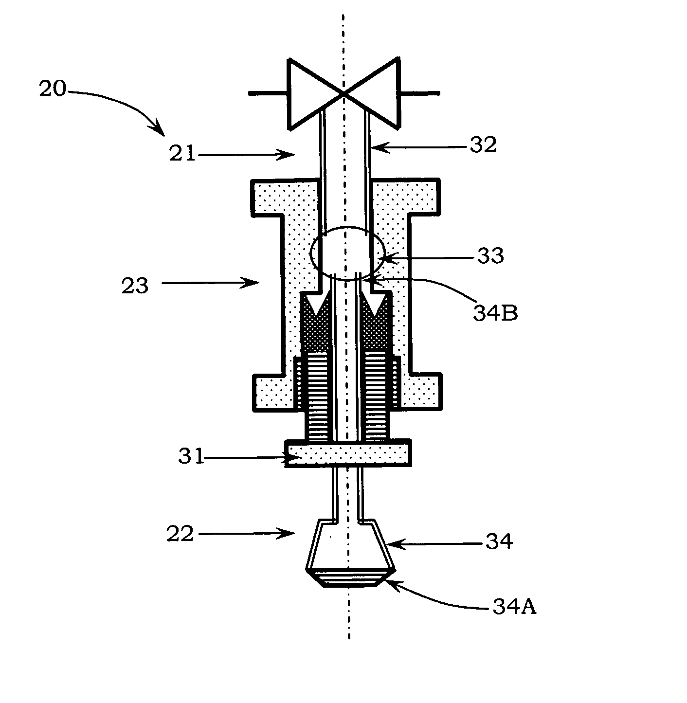
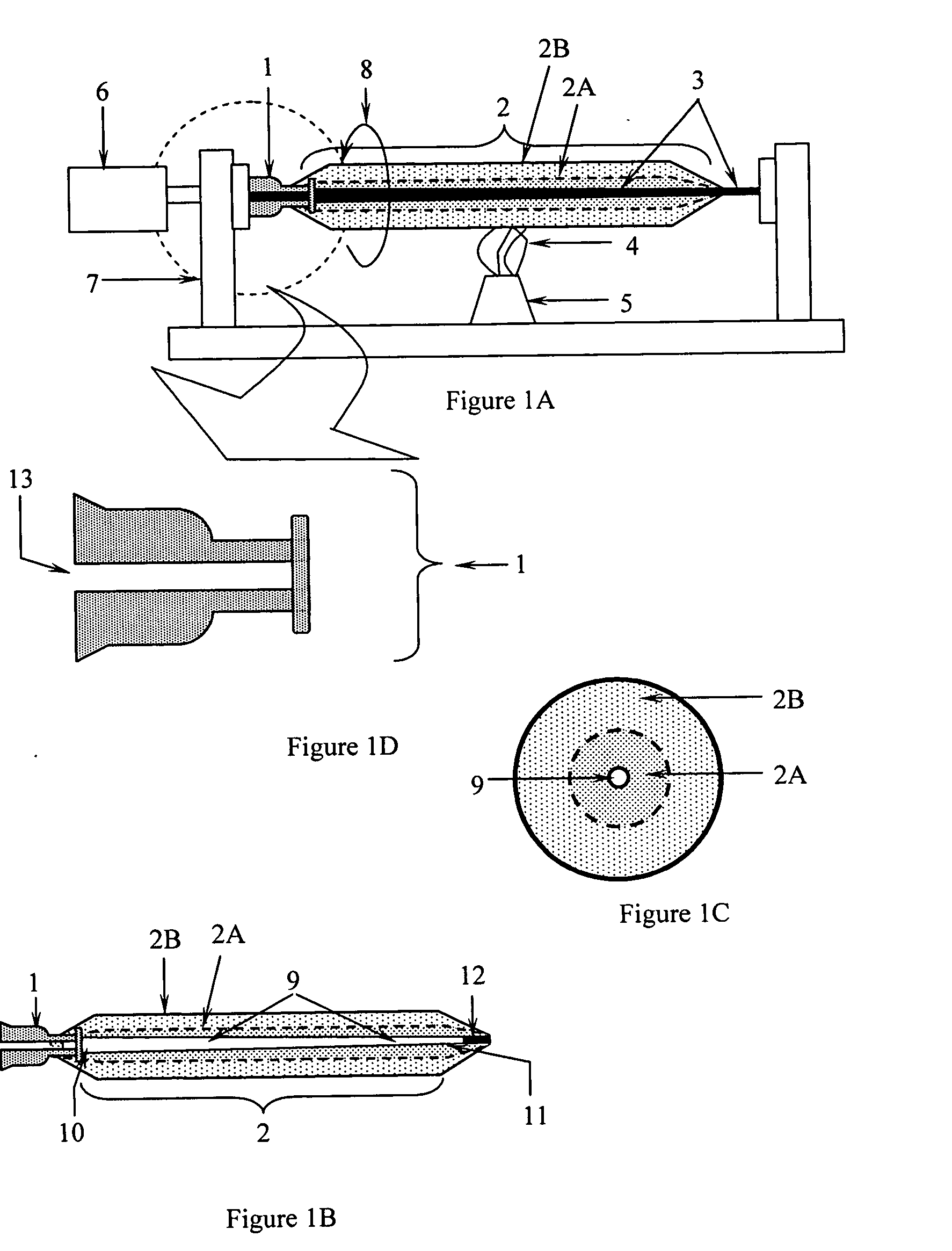
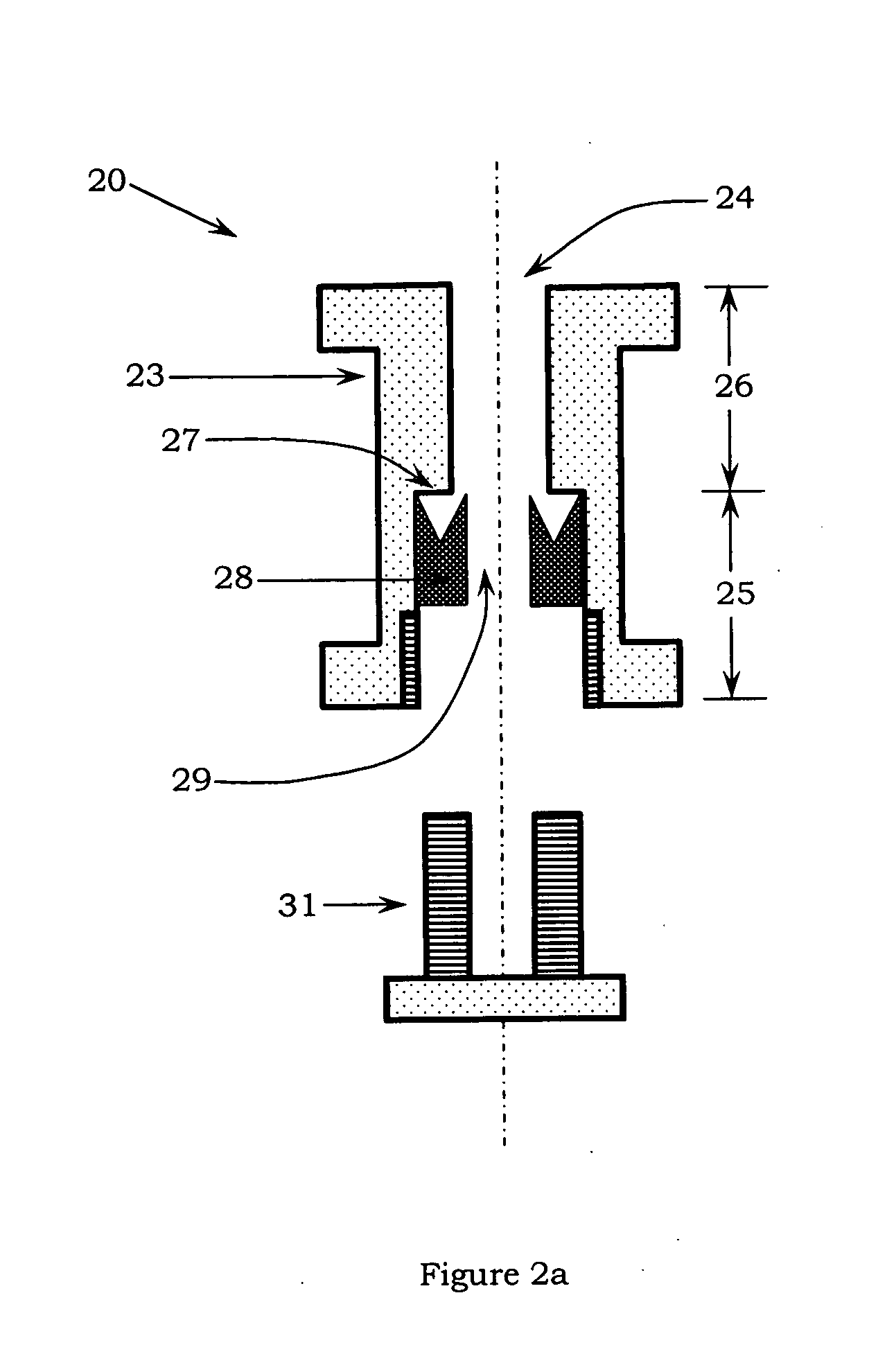
[0120] A hollow soot porous body with outer diameter of 170 mm and having a capillary at the center of about 4 mm (after removing the cylindrical member) was fabricated by ACVD process. This hollow soot porous body was fitted with glass plug at the capillary end remote from the handle. The hollow soot porous body handle was fitted with rotary sealing mechanism having no cooling system in accordance with one of the preferred embodiments of the present invention. It was dried in an atmosphere of chlorine and helium at a temperature of 1000° C. Then the end of the capillary remote from the handle of the preform fitted with a glass plug was heated to a temperature of 1550° C. to cause engagement of glass plug. Thereafter, a vacuum of about 550 mm Hg was applied to the capillary, through the rotary sealing mechanism of present invention. The hollow soot porous body was inserted at an insertion speed of 4.5 mm / min in the sintering furnace. While heating the hollow soot porous body was rot...

example 2

[0122] The method for fabricating the preform and drawing a fiber therefrom was followed as described in Example 1 above. However, the rotary sealing mechanism of U.S. patent '069 was employed for achieving contact between rotating member [rotating hollow soot porous body] and stationary member [connection to vacuum pump]. The attenuation values for the optical fiber drawn by an apparatus emptying rotary sealing mechanism of US '069 are shown in Table II below. It is observed that the attenuation losses for the optical fiber drawn by an apparatus comprising rotary sealing mechanism of US '069 are well above the desired values of 0.34 dB / Km at 1310 nm and 0.20 dB / Km at 1550 nm confirming that the rotary sealing mechanism of US '069 does not work satisfactorily and causes any release of certain particles from its sealing members [the O-rings], and leakage of vacuum from rotary sealing mechanism and contamination of capillary of hollow soot porous body with atmospheric contaminants dur...


PUM

PropertyMeasurementUnit
Fractionaaaaaaaaaa
Nanoscale particle sizeaaaaaaaaaa

Abstract

A rotary seal capable of joining a stationary member with a rotating member is provided, wherein the rotary seal comprises a body having a central hole therethrough, wherein said central hole has stepwise reducing diameter so as to form two part central hole, wherein front part of said central hole has higher inner diameter and rear part of said central hole has lower inner diameter, wherein said front part forms a seat with said rear part of said central hole, wherein said front part of said central hole is capable of accommodating at least one sealing member, and said sealing member is made to sit onto said seat by a screwing member, which when fixed onto body fits into front part of said central hole, and said rear part of said central hole is capable of accommodating connecting member of said stationary member. An apparatus comprising the rotary seal is also provided.

Description

FIELD OF THE INVENTION [0001] The present invention relates to an apparatus and method for fabricating optical fiber preform. Particularly, it relates to a rotary sealing mechanism for apparatus for fabricating optical fiber preform, and apparatus comprising the same. The present invention also relates to method for fabricating optical fiber preform employing apparatus comprising rotary sealing mechanism, and optical fiber produced from such preform, wherein the fiber produced has low attenuation, preferably less than about 0.35 dB / Km in the wavelength range varying from about 1300 nm to about 1625 nm. BACKGROUND OF INVENTION [0002] Optical fibers are inherently versatile as a transmission medium for all forms of information, be it voice, video or data. The primary object of telecommunication industry is to transmit greater amount of information, over longer distances, in shorter period of time. This object can be fulfilled with the optical fibers provided it has low optical attenua...

Claims


Application Information

Patent Timeline
IPC IPC(8): B23B31/30G02B6/02C03B37/018B32B17/06B23B31/10B32B9/00
CPCC03B37/01486Y10T279/12C03B37/01884
Inventor SHAH, SANKETSINGH, CHANDRAVEERSHINDE, NITIN
Owner STERLITE TECHNOLOGIES
Why Eureka
Try Eureka