Rotary support with elastic connection device for installation of electric machines in tubes

a technology of elastic connection and electric machine, which is applied in the direction of magnetic circuit rotating parts, magnetic circuit shape/form/construction, transportation and packaging, etc., to achieve the effects of reducing manufacturing costs, facilitating installation, and increasing temperatur

Inactive Publication Date: 2007-05-03
SIEMENS AG
View PDF20 Cites 28 Cited by
  • Summary
  • Abstract
  • Description
  • Claims
  • Application Information

AI Technical Summary

Benefits of technology

[0010] According to an especially advantageous embodiment, the elastic connection device has one or more components which are made of rubber or similar elastic material, or are coated therewith. The one or more components may hereby constitute formed parts of elastic, rubber-like material or solid rubber. In particular, the formed parts may be configured as O rings. The rubber-like components have the advantage of reduced manufacturing costs and easier installation. Moreover, such rubber components enable insertion of the rotary support deeper into the roll interior.
[0011] According to an embodiment which is also very much preferred, the elastic connection device has one or more components of metal, for example metal springs. The metal components may also be designed as tolerance rings of a shape and radial thickness that can be modified as a result of external pressure. These metal components have the advantage of allowing their use at higher temperatures and of exhibiting in general less wear.
[0012] Advantageously, the hollow-cylindrical body has fixing elements on its outer circumference for securing the elastic connection device. As a result, any formed components of the elastic connection device can be secured upon the outer circumference of the hollow-cylindrical body. Thus, there is no need for the components of the elastic connection device to rely on friction or internal stress to effect self-fixing in circumferential direction or axial direction.
[0013] When installed, the hollow-cylindrical body may moreover form with the tubular structure or the bore channels or passageways in longitudinal direction for circulation of the coolant and, optionally, for forming a closed cooling circuit. Despite centering and torque transmission, a good cooling effect is ensured of the electric motor in the roll interior for example.
[0014] It is also very advantageous to additionally conically shape the elastic connection device in relation to the length axis of the hollow-cylindrical body. In this way, it is easier to insert the rotary support in the roll. As a consequence of the rising squeezing force during insertion in longitudinal direction, the presence of a sufficient torque transmission is still ensured.

Problems solved by technology

A problem relating to the securement of the drives in the rolls involve longitudinal joints or weld seams in the roll interior for maintaining integrity of the rolls.
Longitudinal weld seams cause also centering problems during mounting of the rotary support in the tube.

Method used


Image

  • Rotary support with elastic connection device for installation of electric machines in tubes
  • Rotary support with elastic connection device for installation of electric machines in tubes
  • Rotary support with elastic connection device for installation of electric machines in tubes

Examples


second embodiment

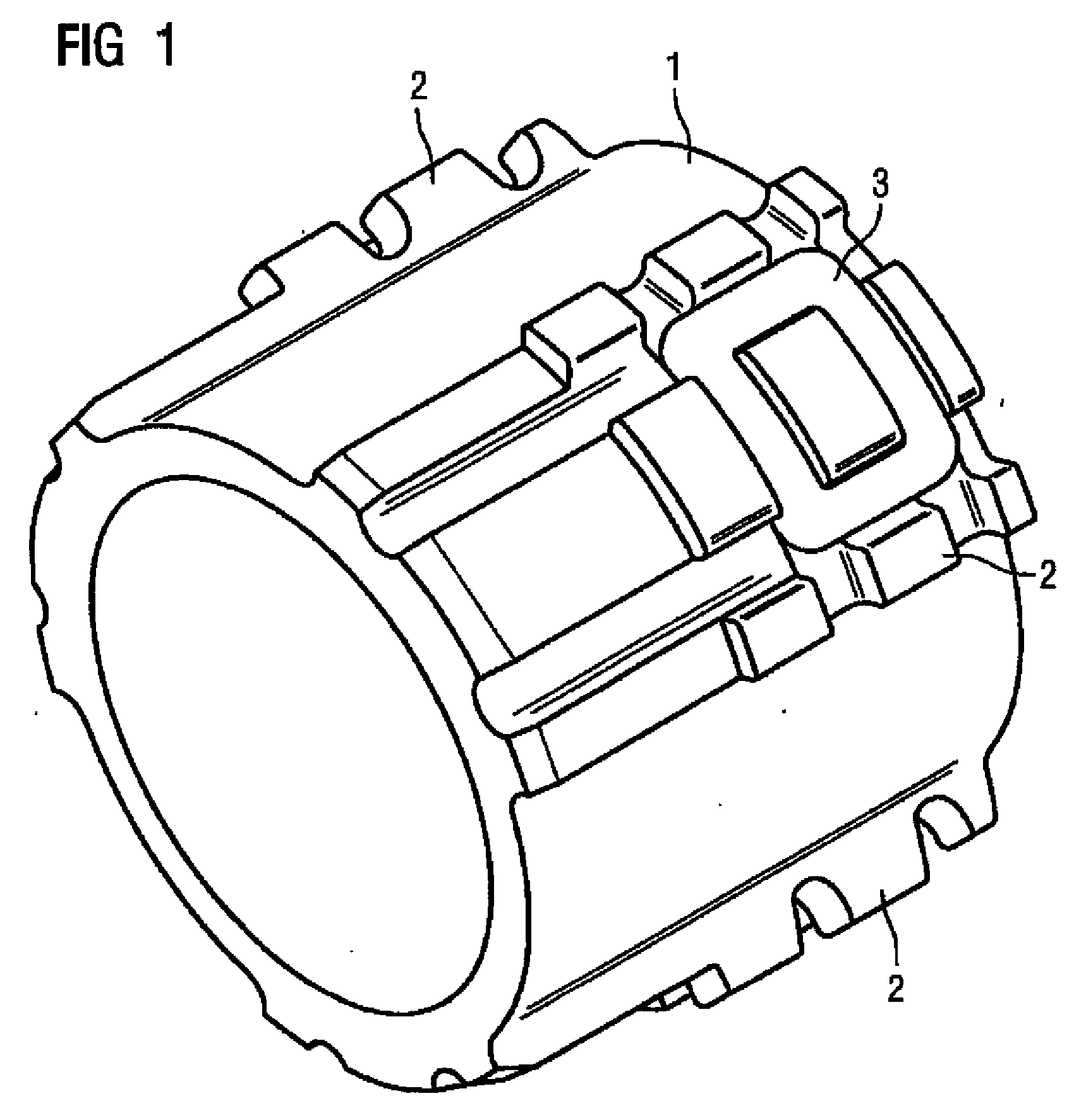
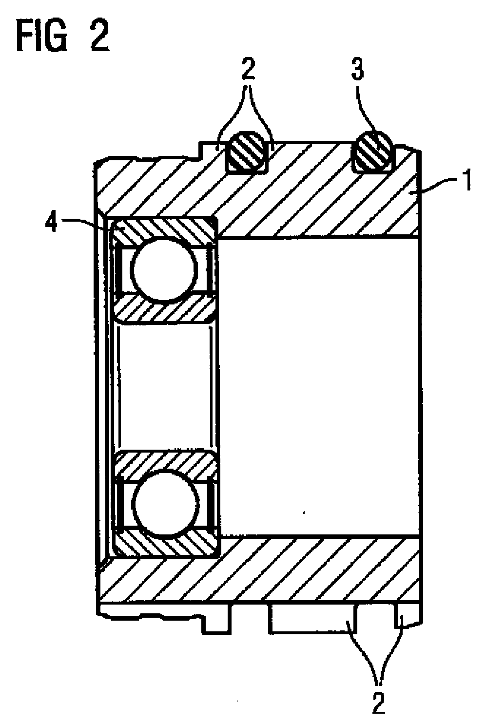
[0032] According to the present invention, as shown in FIG. 4, two O rings 7 are used as elastic connection device in complete surrounding relationship to the circumference of the hollow-cylindrical body 1. A comparison with FIG. 1 shows that the fixing elements 2 have the same shape in both embodiments. Thus, a greater flexibility is established with respect to attachment of different O rings.

[0033] In the embodiment of FIG. 4, the O rings 7 extend also through the regions between the groups of fixing elements 2. This means that the coolant flow is slightly obstructed by the O rings 7, although not entirely suppressed. Thus, this embodiment can be used when cooling of the drive is less critical.

[0034] In both embodiments illustrated above in FIGS. 1 to 4, three support points or areas are respectively spaced upon the circumference. Of course, any other number of support points may also be selected. In addition, the supports may have any length in longitudinal direction. The diamet...

third embodiment

[0035] According to the present invention, a tolerance ring made of metal is used as elastic connection device. Such a rotary support is shown in FIG. 5. The tolerance ring 8 is situated in a groove formed in the hollow-cylindrical body 1. The tolerance ring 8 is made of corrugated sheet metal so that its overall configuration but also its radial thickness can be modified. Such a tolerance ring also ensures a torque transmission, an axial securement as well as centering and attenuation of the rotary support in relation to the tube as a result of a force-fitting installation. These tolerance rings are standard components and available from Mannesmann-Star for example.

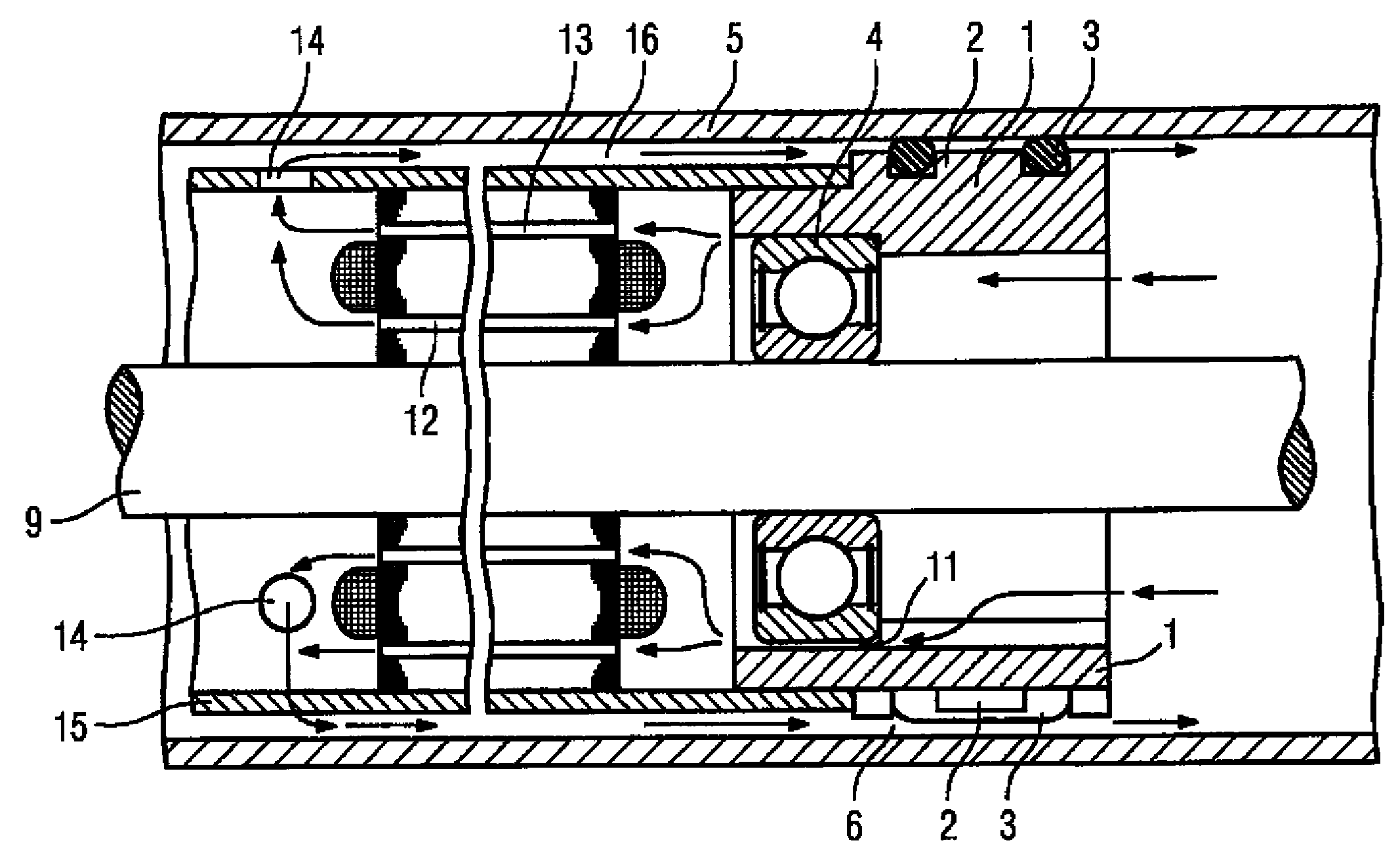
[0036]FIG. 6 shows a cross section through a rotary support, installed in a tube 5. The hollow-cylindrical body 1 is pushed into the tube 5. The tolerance ring 8 establishes the force-fitting connection between both these components. The rotary support is supported with the aid of a bearing 4 upon a hollows axle 9. Route...


PUM


Abstract

Torque transmission between a tube and a drive unit mounted in the tube is ensured with the aid of a component which is optimized for installation while providing a sufficient centering effect. A rotary support is hereby provided which is constructed as a hollow cylindrical body (1). An elastic connection device (3), e.g. an O ring which is disposed on the outer circumference of the hollow cylindrical member (1) in a defined arrangement, is used for elastically connecting the hollow cylindrical member (1) to the tube. The elastic connection device (3) has a centering and damping effect while ensuring the torque transmission, and channels (6) ensure a coolant flow passage/cooling circuit.

Description

BACKGROUND OF THE INVENTION [0001] The present invention relates to a rotary support for mounting an electric machine in a tubular structure or a bore, having a hollow-cylindrical body which can be arranged in radial direction between the electric machine and the tubular structure or the bore, for torque transmission from the electric machine to the tubular structure or the bore. [0002] Rolls with integrated drive are oftentimes used for conveyor belts. The motor or the motor with transmission, optionally together with control and brake, is hereby mounted in the roll. These components are to be secured axially and radially in the roll and have to transmit thereto at times high torques. [0003] A problem relating to the securement of the drives in the rolls involve longitudinal joints or weld seams in the roll interior for maintaining integrity of the rolls. Thus, so called rotary support, in which the drives run, can be mounted through interference fit only in a very complicated mann...

Claims


Application Information

Patent Timeline
Patent Type & Authority Applications(United States)
IPC IPC(8): H02K5/24H02K9/00H02K1/22B65G23/08B65G39/00B65G39/09
CPCB65G23/08B65G39/09
Inventor KIRCHNER, KLAUS
Owner SIEMENS AG
Why Eureka
Try Eureka