Fuel cell system, method of starting fuel cell system

Active Publication Date: 2007-05-03
PANASONIC CORP
View PDF5 Cites 36 Cited by
  • Summary
  • Abstract
  • Description
  • Claims
  • Application Information

AI Technical Summary

Benefits of technology

[0035] In accordance with the present invention, the interior of the fuel cell is exposed to an atmosphere of moistened raw material gas at a proper time, making it possible

Problems solved by technology

Firstly, even if the fuel cell is sealed in such an arrangement that it is blocked off the external atmosphere, in the case where the fuel cell is stored over a certain period of time (e.g., about 15 hours to 3 days), it is likely that air (oxygen gas) can leak and enter inside of the fuel c

Method used


Image

  • Fuel cell system, method of starting fuel cell system
  • Fuel cell system, method of starting fuel cell system
  • Fuel cell system, method of starting fuel cell system

Examples


embodiment 1

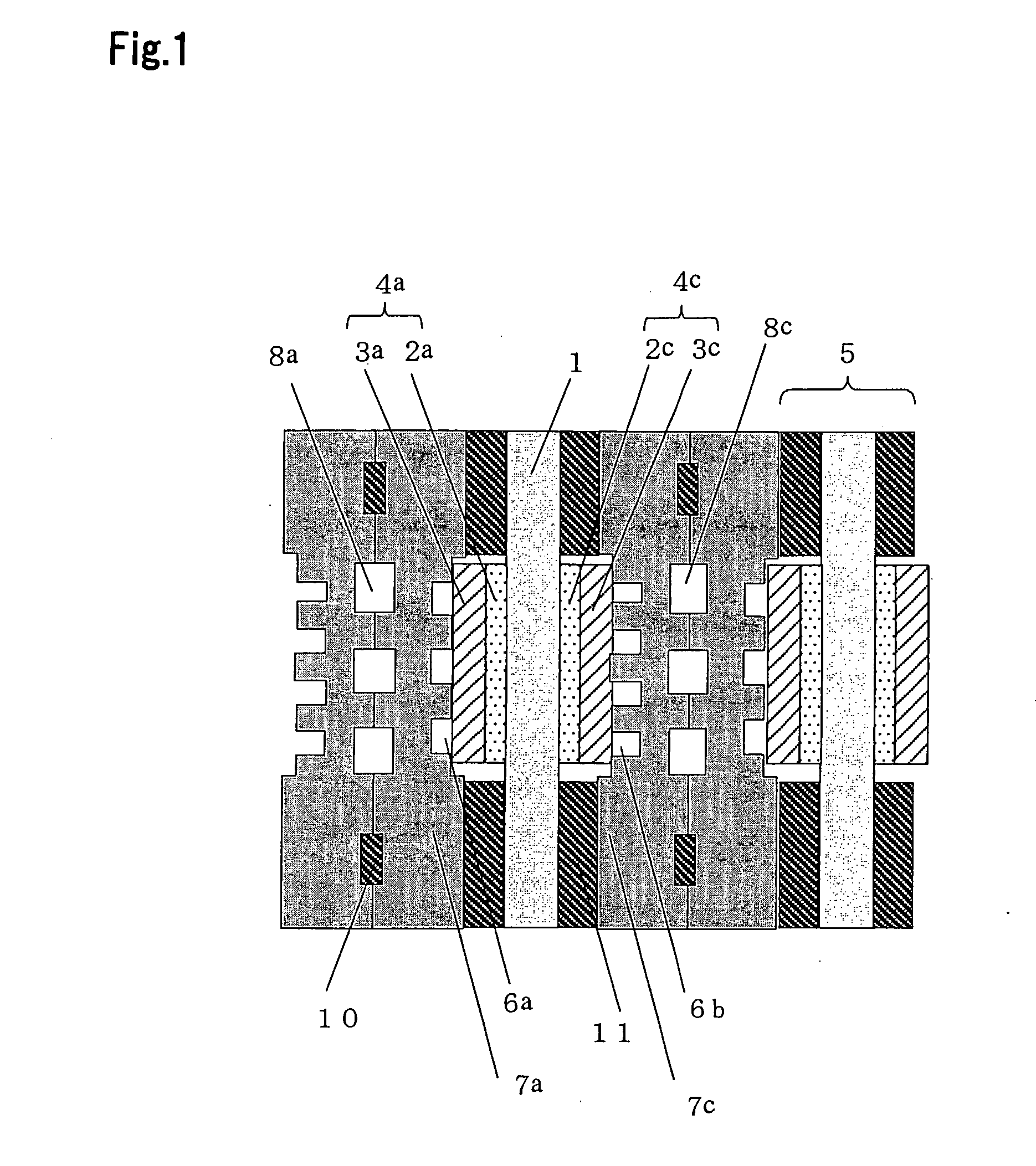
[0209]FIG. 1 depicts the basic configuration of a polymer electrolyte type fuel cell as an example of the fuel cell according to Embodiment 1 of implementation of the present invention. A fuel cell is an apparatus to cause a fuel gas containing at least hydrogen and an oxidizing agent gas containing oxygen such as air to react with each other electrochemically, thereby generating electricity and heat at the same time. As an electrolyte 1 there may be used, e.g., a polymer electrolyte membrane which selectively transports hydrogen ion. On the both surfaces of the electrolyte 1 is disposed a catalytic reaction layer 2 comprising as a main component a carbon powder having a platinum-based metal catalyst supported thereon. Reactions represented by (chemical formula 1) and (chemical formula 2) occur on the catalytic reaction layers 2a and 2c. The fuel gas containing at least hydrogen undergoes reaction represented by (formula 1) (hereinafter referred to as “anode reaction”) and the hydro...

embodiment 2

[0246] The operation of the fuel cell system according to Embodiment 2 of implementation of the present invention will be described below, and an embodiment of the method of suspending the fuel cell system of the present invention will be thus described in connection with the flow chart shown in FIG. 5. The basic configuration and operation of the present embodiment are the same as that of Embodiment 1. The operating method will be described in detail below. The “operating step” of the present embodiment is the same as that of Embodiment 1.

[0247] Subsequently, a “suspension step 1” was executed. At the “suspension step 1”, the blower 39 is firstly suspended and adjustment is made such that the dispensing valve 60 causes the purified fuel gas to flow into both the bypass pipe 55 and the purified gas pipe 36 and the dispensing value is switched so that the gas flowing into the stack 38 is composed of only the gas from the bypass pipe 55.

[0248] In this manner, the oxidizing agent gas...

embodiment 3

[0252] The operation of the fuel cell system according to Embodiment 3 will be described below, and an embodiment of the method of suspending the fuel cell system of the present invention will be thus described in connection with the flow chart shown in FIG. 6. The basic configuration and operation of Embodiment 3 are the same as that of Embodiment 1 or 2, but the configuration thereof is such that the bypass pipe 61 and the on-off valve 62 are omitted.

[0253] The operating method will be described in detail below. The basic conditions of “operating step” under which electricity generation and heat generation are conducted are the same as that of Embodiment 1. Herein, the current drawn from the stack 38 at the electric power circuit portion 43 is controlled by the control portion 44 according to the magnitude of consumption of electric power at houses, etc. When the electric power generated by the fuel cell system is no longer consumed, the current drawn from the stack 38 decreases,...


PUM


Abstract

Problems of acceleration of drying of electrolyte membrane and local reaction, etc. can be properly coped with to attain the stabilization of performance of fuel cell.
There are provided a fuel cell 121 which generates electric power from a fuel gas and an oxidizing agent gas, a fuel gas feed pipe 161 and a first switch valve 129 as fuel gas supplying unit which supplies the said fuel gas into the said fuel cell on the anode side thereof, an oxidizing gas supplying pipe 162 and a second cut-off valve 131 as oxidizing agent gas supplying unit which supplies the said oxidizing agent into the said fuel cell on the cathode side thereof, a raw material gas supplying pipe 151 and a third switch valve 143 as raw material gas supplying unit which supplies raw material of the said fuel gas into the fuel cell and a control portion 127 which controls the supply of the said fuel gas, the supply of the said oxidizing agent and the supply of the said raw material and the control portion 127 controls during the starting of electricity generation of the fuel cell 121 such that the said raw material gas supplying unit purges the fuel cell 121 at least on the cathode side thereof with the said raw material gas before the oxidizing agent gas supplying unit and the fuel gas supplying unit supply the fuel gas and the said oxidizing agent gas into the fuel cell 121, respectively.

Description

RELATED APPLICATIONS [0001] This application is the U.S. National Phase under 35 U.S.C. § 371 of International Application No. PCT / JP2004 / 012458, filed Aug. 24, 2004, which in turn claims the benefit of Japanese Application Nos. 2003-299581, filed Aug. 25, 2003; 2003-306621, filed Aug. 29, 2003; 2003-350058, filed Oct. 8, 2003; 2003-415579, filed December 12, 2003; and 2004-011550, filed Jan. 20, 2004, the disclosures of which Applications are incorporated by reference herein in their entirety.TECHNICAL FIELD [0002] The present invention relates to a fuel cell system and a method of starting same. BACKGROUND ART [0003] The configuration and operation of a conventional ordinary solid polymer electrolyte type fuel cell will be described in connection with FIGS. 1, 2 and 7. FIG. 1 depicts the basic configuration of a polymer electrolyte type fuel cell (hereinafter referred to as “PEFC”) among the conventional fuel cells. A fuel cell is an apparatus to cause electrochemical reaction of ...

Claims


Application Information

Patent Timeline
IPC IPC(8): H01M8/04H01M8/06H01M8/10
CPCH01M8/04231H01M8/04365H01M8/04388H01M8/04395H01M8/04425H01M8/04559H01M8/04649H01M8/04746H01M8/04776H01M8/04955H01M8/0606H01M2008/1095Y02E60/50
Inventor MORITA, JUNJIUCHIDA, MAKOTOSUGAWARA, YASUSHIURATA, TAKAYUKIKOSAKO, SHINYAUMEDA, TAKAHIROSHIBATA, SOICHITSUJI, YOICHIROOZEKI, MASATAKANAKAMURA, AKINARITANAKA, YOSHIKAZU
Owner PANASONIC CORP
Why Eureka
Try Eureka