Pulsed Field Gel Electrophoresis chambers, accessories and methods of use for the separation of DNA molecules

Inactive Publication Date: 2007-05-10
CENT NACIONAL DE INVESTIGACIONES CIENTIFICAS (CINC)
View PDF2 Cites 14 Cited by
  • Summary
  • Abstract
  • Description
  • Claims
  • Application Information

AI Technical Summary

Benefits of technology

[0085] They also permit to perform co-electrophoresis of many or few samples in multiple minigels, as well as to reduce the running time duration maintaining the resolution among the molecules and the high-throughput capacity of analysis.
[0295] Gels of different sizes can be placed in CHEF minichambers. To retain the gel 61 (FIG. 12) in a given position during the electrophoresis, a plastic or acrylic rectangular base plate 63 is used. Square flanges 62, are placed on the base plate 63. Each square flange 63 is placed at each corner of a rectangular or square contour where the gel 61 will be retained. The separations between the square flanges 62 are as the same dimensions (length and width) of the gel 61 that will be placed on said contour. The maximum height of the square flange 62 should be 0.2 cm, to avoid the attenuation and distortion of the electric field generated in the chamber.

Problems solved by technology

The systems differ among them by the complexity of the electronics to energize the electrodes and to switch the orientation of the electric field.
Due to the absence of a theory that predicts the inversion mobility in FIGE under any experimental conditions, such inversion limits the use of these chambers to analyze the size of DNA molecules separated and to compare their band patterns.
In FIGE the size markers can also suffer mobility inversion and, as mentioned above, there is no theory capable to predict the moment and conditions of appearance of such inversion.
These are serious drawbacks of FIGE chambers, especially to compare many samples, for instance, in molecular epidemiology studies.
Large heat generation in the electrophoresis impedes the reduction of the duration of electrophoresis by increasing the electric field strength.
It has been stated that the use of elevated voltages or high temperatures broaden and make diffuse the bands of the electrophoresis pattern, rendering poorly resolved bands.
Nevertheless, a common disadvantage of the CHEF and TAFE equipments is that the chambers are unnecessarily large, because their dimensions have not been optimized yet, particularly when thin sample plugs are used.
III) The equipments are not economical, because large amount of expensive reagents (such as Tris and agarose) and biological samples are used.
The latter might impede certain applications (for instance in clinical diagnosis).
An excessive increase of heat evolved will broaden and make the bands diffuse and will provoke distortion of the electrophoresis pattern and even entrapment of DNA molecules in the pores of the gel and the complete absence of migration.
Furthermore, they save laboratory bench space.
In addition, the use of thick samples does not improve the quality of the electrophoresis pattern and does not reveal more bands.
Therefore, they can inherit errors of the equipments from which they were designed.
In fact, the mini-equipments inherited from the large chambers an open system for the preparation of the gel and the absence of a proper system for attenuating turbulences of the buffer flowing throughout the chamber.
That is, the question whether this volume of buffer is enough to attenuate the turbulences during its circulation, or whether the irregularities in the gel and the differences in dimensions of the plugs influence the quality of the bands patterns that are obtained, are not resolved yet.
These troubles increase with miniaturization, because miniaturization magnifies the manufacture errors.
If the separation between the electrodes with opposite polarity is not optimal, for instance, if it is too large, then the dimensions of the gel, the chamber and the number of samples that can be applied in those gels will not be optimal.
If the plugs do not have the proper thickness and size, an excessive quantity of gel will be used and large electrophoresis time will be consumed.
In addition, the shape and distribution of the dimensions of the chambers as well as the existence of a single UEZ region determines that the reagents consumed in these chambers will not be used optimally.
From the above reasons, it is concluded that: Large chambers of the current PFGE systems are not optimal, because the separation between electrodes with opposite polarity is unnecessary large and the same amount of reagents is used, independently on the number of samples to be studied.
The chamber dimensions are not optimal.
They may affect the proper functioning of the systems.
Therefore, the comparison of the resulting band patterns will not be reliable.
Then, these three chambers have insufficiencies in their capacity to simultaneously analyze more than 8, 20 or 40 samples, respectively, or are insufficient the possibilities to increase the capacity of analysis.
However, in the TAFE system, the samples loaded into the wells formed by the two combs would not be subjected to the same electric field nor to identical reorientation angle; thus molecules of similar size would migrate different distances in the gel and the bands patterns would not be comparable.
These dielectrics considerable slow down the electrophoresis runs.
Then, in this type of chambers is impossible to increase the electric field strength to reduce the electrophoresis time.
Low electric fields unnecessary enlarge the duration of PFGE experiments, fact that reduces the spectrum of applications of these chambers in the fields of the science and technology that require the rapid obtainment of results.
However, such broad UEZ would need a very wide minigel, which would present difficulties in its casting and handling.
Additionally, several minigels could be accommodated, but according to formula I (see forward), this chamber would not be efficient when analyzing a small number of samples.
The reagents used in PFGE experiments are expensive.
This is impossible in chambers of a single UEZ because they use a constant volume of reagents.
Hence, the volume of reagents used by the TAFE Geneline I, Geneline II and MiniTAFE chambers is constant and independent on the number of samples to be analyzed, fact that impedes its optimal use.
In addition, the buffer solution becomes exhausted during electrophoresis.
The miniequipments previously reported are not optimum, because they do not have any system to attenuate turbulences of the buffer solution flowing through the chamber, neither to prepare gel without irregularities nor to form thin sample plugs of similar sizes and shapes.
However, the quality of the band patterns and the experimental reproducibility are affected by variations in the voltage and other factors.
They are: The chambers do not have simple devices to attenuate the turbulences of the buffer flowing through the chamber and the external heat exchange.
The accessories to cast the gels do not avoid the formation of irregularities and defects in the electrophoresis gel.
There are not devices to achieve a good alignment of the sample plugs in the migration origin either.
There are not devices to warrant maintaining the electrodes stretched.
However, at a given buffer injection velocity, turbulences in the chambers are generated.
The turbulences are increased if the buffer is circulated at high flow velocities.
However, this system is not efficient to attenuate buffer turbulence, mainly when high flow velocity is used.
Neither the TAFE nor the miniequipments have any system for attenuating the turbulences of the buffer flowing throughout the chamber, which is a disadvantage.
It is easy to sense that the turbulences are more harmful in the miniequipments that use less amount of buffer.
However, the miniequipments for PFGE are relatively recent, maybe for this reason the development of a system for attenuating the turbulences of the buffer flowing through these chambers has not been a focus of attention.
The mold to prepare the TAFE gel has a lid, but it has not accessories to avoid the meniscus formation among the teeth of the comb.
The gel wells are the origin of migration of the molecules; consequently, if the irregularities in these zones provoke changes in the velocity of migration of the molecules, the migration boundaries will be distorted.
However, the effect of the shape and dimension inequalities of the sample plugs upon the electrophoresis patterns has not been thoroughly studied.
However, these molds do not include devices to cut the sample plugs with identical shape and dimensions and matching with the gel wells.
The flaws preparing the sample plugs and troubles in their alignment in the gel wells are exactly reproduced in the bands separated in the patterns, and might provoke tilted and undulated bands.
Besides that sample plug preparation could be longer using this processing chamber, said mold does not have associated a device to cut the sample plugs and, thus, plugs of similar sizes are not warranted to be obtained.
Them, the system used in the TAFE to set the electrodes has the disadvantage that to pull tight the electrode the experimenter must dismount the electrode from the lid and this is very difficult.
However, it is not warranted that these electrodes are maintained stretched and consequently slight deformations of the lines of force of the electric field can occur.
Besides, it represents an additional expense of platinum wire and them the chambers are more expensive.
Despite of the mentioned advantages, the refereed equipments have inadequacies that limit their application in the analysis of numerous samples.
They also recommend to be considered that both algorithms can give erroneous results such as DNA mobility inversion in the mid-range of the gel, when extremely wide size ranges are entered in both algorithms.
However, this relation is only valid in some experimental conditions and does not predict the resolution between any pair of molecules.
It means that they do not generated methods that permit the easy selection of the experimental conditions that separate a given group of molecules.
There is not a secure method to predict the pulse and run times hat should be applied at any conditions.

Method used


Image

  • Pulsed Field Gel Electrophoresis chambers, accessories and methods of use for the separation of DNA molecules
  • Pulsed Field Gel Electrophoresis chambers, accessories and methods of use for the separation of DNA molecules
  • Pulsed Field Gel Electrophoresis chambers, accessories and methods of use for the separation of DNA molecules

Examples


example 1

Chambers that have Multiple useful Electrophoresis Zones (UEZ): Type I TAFE multiminichamber

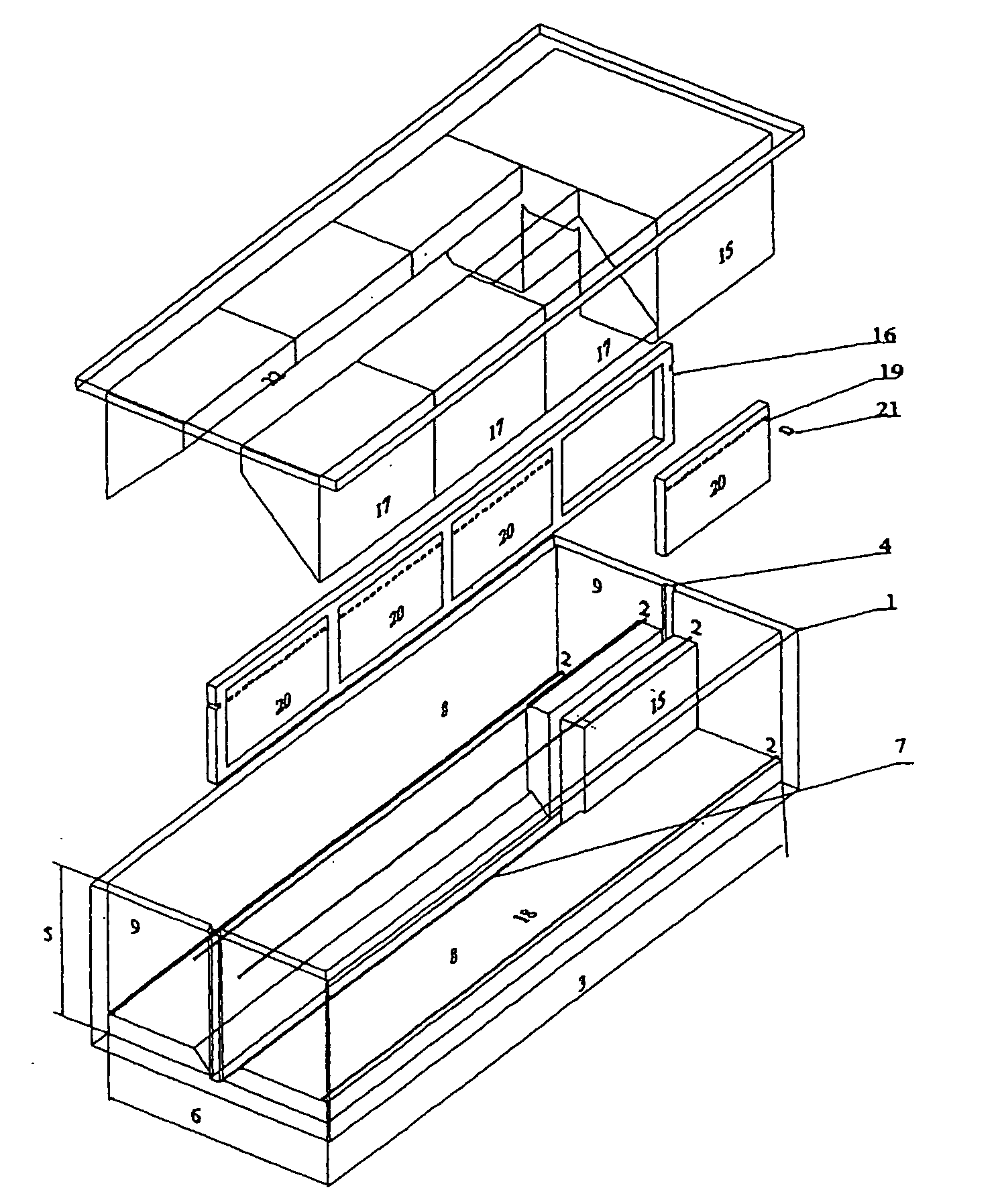
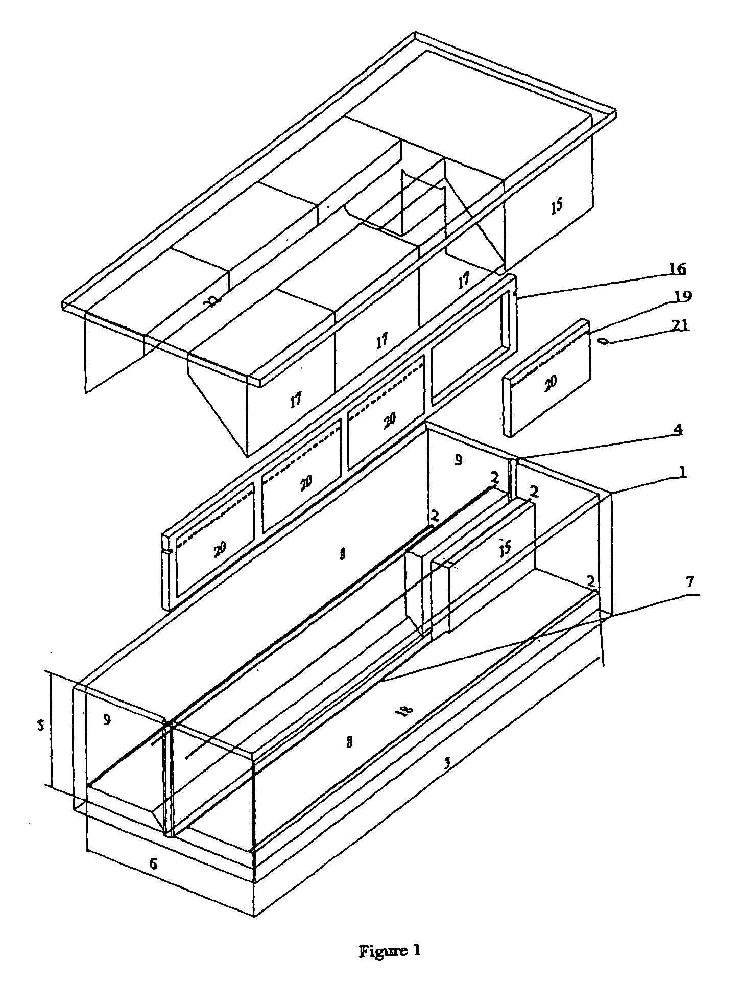
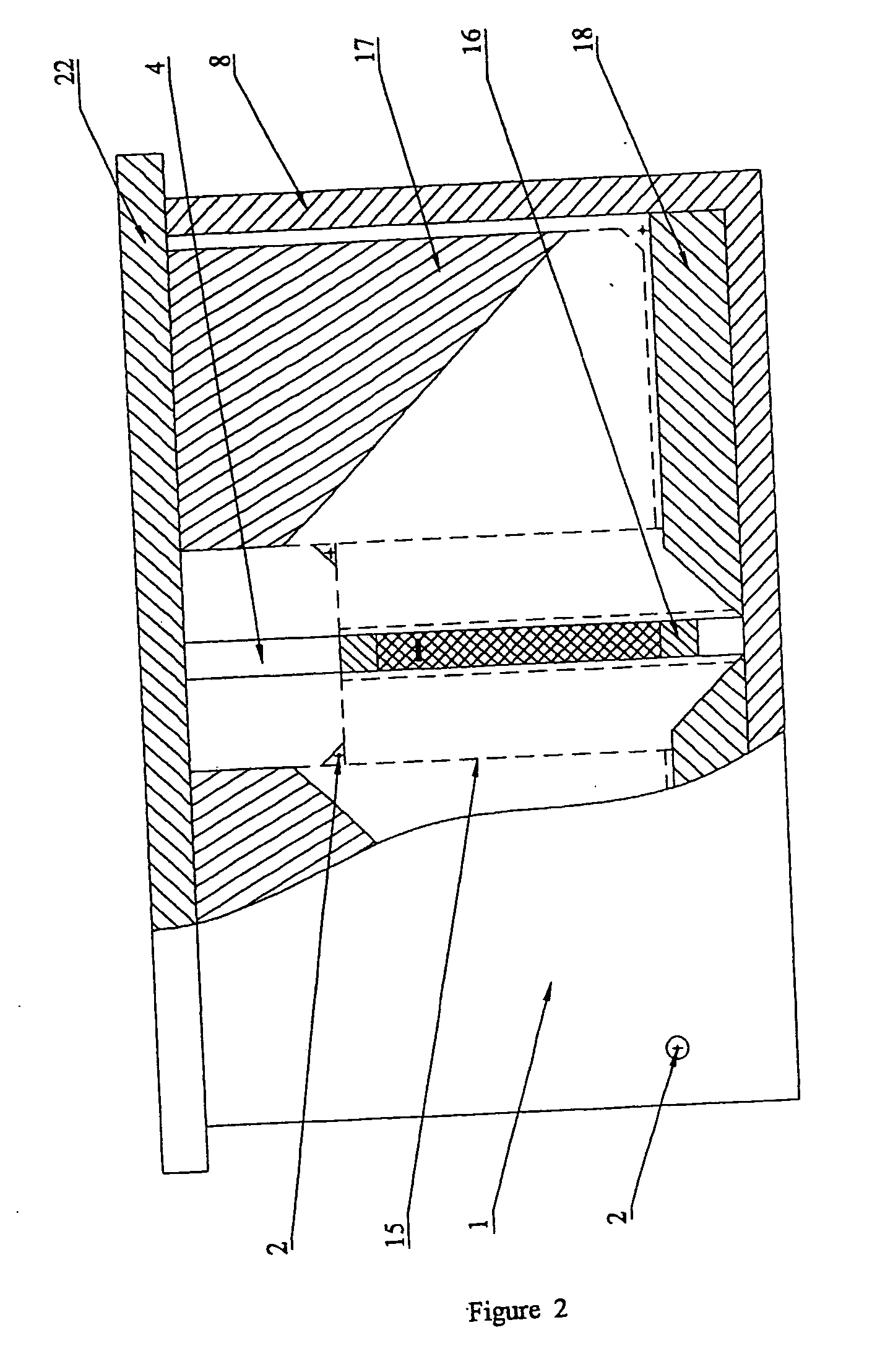
[0257] In the FIG. 1 is shown an exploded isometric view of a scheme of the chamber 1. In the view is shown the four electrodes 2 of the conventional TAFE arrangement. The width 3 of the chamber is 316 mm, the height 5 is 74 mm and the depth 6 is 114 mm. The frontal 8 and the side 9 walls of the chamber are also pointed out. The bottom 18 of the chamber has an excavation 7 that accommodates the frame 16 carrying the cast minigels 20 that the chamber uses. In the side walls 9 are the milled grooves 4 through which the frame 16 slides into the chamber. The frame dimensions are 48 mm tall by 320 mm wide by 5 mm thick. This frame supports four minigels 20 of 38 mm height and 71.25 mm width. The wells 21 for loading the samples in the minigels 20 are formed by inserting a comb that has teeth of 3 mm width and spaced 2 mm.

[0258]FIG. 1 shows a three-dimensional scheme of the lid 22, of the blocks ...

example 2

Chambers that have Multiples useful Electrophoresis Zones: Type II TAFE Multiminichamber

[0269]FIGS. 4-7 show several views of a type II chamber that has 3 removable mini-platforms of electrodes.

[0270] The FIG. 4 shows a view in exploded form of a side section of the chamber 34, the removable electrode mini-platform 25, the frame 30 that supports the gel 31 and the sample plugs 36. In the mini-platform 25, the cathodes 26 are at the bottom of the chamber, whereas the anodes 27 are at the top (inverted TAFE configuration). The outer walls 28 play a role similar to the blocks 17 of the type I chambers (FIGS. 1 and 2), i.e. said walls eliminate the NEZ regions. In the middle of the electrode mini-platform is located the groove 29 through which is slid the frame 30 that contains the minigel 31 of the mini-platform. The pieces 40 of the mini-platforms 25 have the ducts 41 through which the tubing pass to circulate the buffer solution throughout the chamber.

[0271] It is also shown the f...

example 3

Chambers with Single useful Electrophoresis Zone: minichamber CHEF

[0276] In the FIG. 8 is shown a scheme of minichamber CHEF. Inside a hexagonal array 60 of eighteen electrodes is placed a gel 61 of agarose or other material able to polymerize and form a matrix. The gel 61 is retained in its position with the squares 62 glued to a base plate 62 that is introduced into a depression 69 excavated in the floor of the chamber. Into the gel 61, are loaded the sample plugs 64 which are formed of the same material of said gel and contain immobilized chromosome-sized DNA molecules. Sample plugs 64 are loaded in such a way that, after setting the electric field at the selected intensity and switching its direction of application, the molecules are separated according to their sizes, giving as results reproducible band patterns among the different lanes of the gel. The chamber is filled with the buffer solution to permit the molecules to migrate.

[0277] The temperature, pH, concentration and ...


PUM

PropertyMeasurementUnit
heightaaaaaaaaaa
heightaaaaaaaaaa
thicknessaaaaaaaaaa

Abstract

Methods of use, accessories and chambers, optimal for performing Pulsed Field Gel Electrophoresis (PFGE) of DNA molecules in ‘Contour Clamped Homogeneous Electric Field’ (CHEF) and ‘Transversal Alternating Field Electrophoresis’ (TAFE) systems, are provided herein. DNA molecules are rapidly separated in the minigels of these chambers. The sizes of chambers and accessories are determined by the separation between the opposite polarity electrodes; which is comprised between 6.2 and 15 cm. Reproducibility of molecule separation is achieved because the accessories warrant homogeneous electric resistance in the buffer and minigels. Chambers allow a high-throughput sample format using the reagents efficiently. It is attained excluding the non-useful electrophoresis zones. For a better optimization, TAFE chambers have several useful electrophoresis zones (UEZ), each carrying a minigel. One or more UEZ can be activated at will in the electrophoresis, to vary the number of minigels, the number of samples and the amount of buffer among the experiments. TAFE chambers having ‘inverted electrode configuration’ with the cathodes at their bottom are presented.

Description

REFERENCE TO RELATED APPLICATION [0001] The present invention is related to the field of Molecular Biology and more particularly, it refers to Pulsed Field Gel Electrophoresis chambers of the ‘Contour Clamped Homogeneous Electric Field’ (CHEF) and ‘Transversal Alternating Field Electrophoresis’ (TAFE) systems. This invention is also related to the use of these chambers for the separation of DNA molecules and a method for the selection of the conditions of electrophoresis. BACKGROUND OF THE INVENTION [0002] Pulsed field gel electrophoresis (PFGE) dates from 1984, when Schwartz D. C. and Cantor C. (Cell, 37, 67-75, 1984; U.S. Pat. No. 4,473,452) observed that applying electric pulses that periodically alternated their direction in a certain angle in relation to an agarose gel, large intact DNA molecules were resolved as band patterns. The authors also determined that the separations of the molecules essentially depended on the duration of the electric pulses. Later, it was determined ...

Claims


Application Information

Patent Timeline
Patent Type & Authority Applications(United States)
IPC IPC(8): G01N27/00G01N27/447
CPCG01N27/44704G01N27/44773
Inventor RIVERON ROJAS, ANA MARIALOPEZ CANOVAS, LILIAARENCIBIA DIAZ, OSCARHERRERA ISIDRON, JOSE ALFREDOPEREZ PEREZ, GABRIELOROZCO OROZCO, ESTHERCANINO RAMOS, CARLOS ALBERTOBATISTA SANTILER, LUIS MARIANOGIGATO PEREZ, REGNARRUIZ ESQUVEL, LEONARDONOA BLANCO, MARIA DOLORESJAVERT HIGGINSON, ELISA
Owner CENT NACIONAL DE INVESTIGACIONES CIENTIFICAS (CINC)
Why Eureka
Try Eureka