Method and Structure for Integrated Energy Storage Device

Inactive Publication Date: 2007-05-10
YANG XIAO CHARLES
View PDF6 Cites 23 Cited by
  • Summary
  • Abstract
  • Description
  • Claims
  • Application Information

AI Technical Summary

Benefits of technology

[0006] The present invention relates to a method and device for fabricating an integrated flywheel device using semiconductor materials and IC/MEMS processes. Conventional flywheels deploy high tensile strength and light weight carbon composite materials to achieve high energy storage/we

Problems solved by technology

The rate at which energy can be exchanged into or out of the battery is limited only by the motor-generator design.
Conventional flywheel energy storage devices are intricate electromechanical control systems.
They are complex and costly to construct and maintain.
Furthermore, high performance flywheels deploy expensive composite materials which outgas and affect

Method used


Image

  • Method and Structure for Integrated Energy Storage Device
  • Method and Structure for Integrated Energy Storage Device
  • Method and Structure for Integrated Energy Storage Device

Examples


Embodiment Construction

[0015] According to the present invention, techniques for manufacturing objects are provided. More particularly, the invention provides a method and device for fabricating an integrated flywheel device using semiconductor materials and IC / MEMS processes. As illustrated in Prior Art diagrams, a conventional flywheel energy storage device has a flywheel member coupled to a permanent magnet of a motor / generator. When storing energy, the motor spins the flywheel to high speed converting electrical energy to kinetic energy. When releasing energy, the flywheel spins the generator converting kinetic energy back to electrical energy.

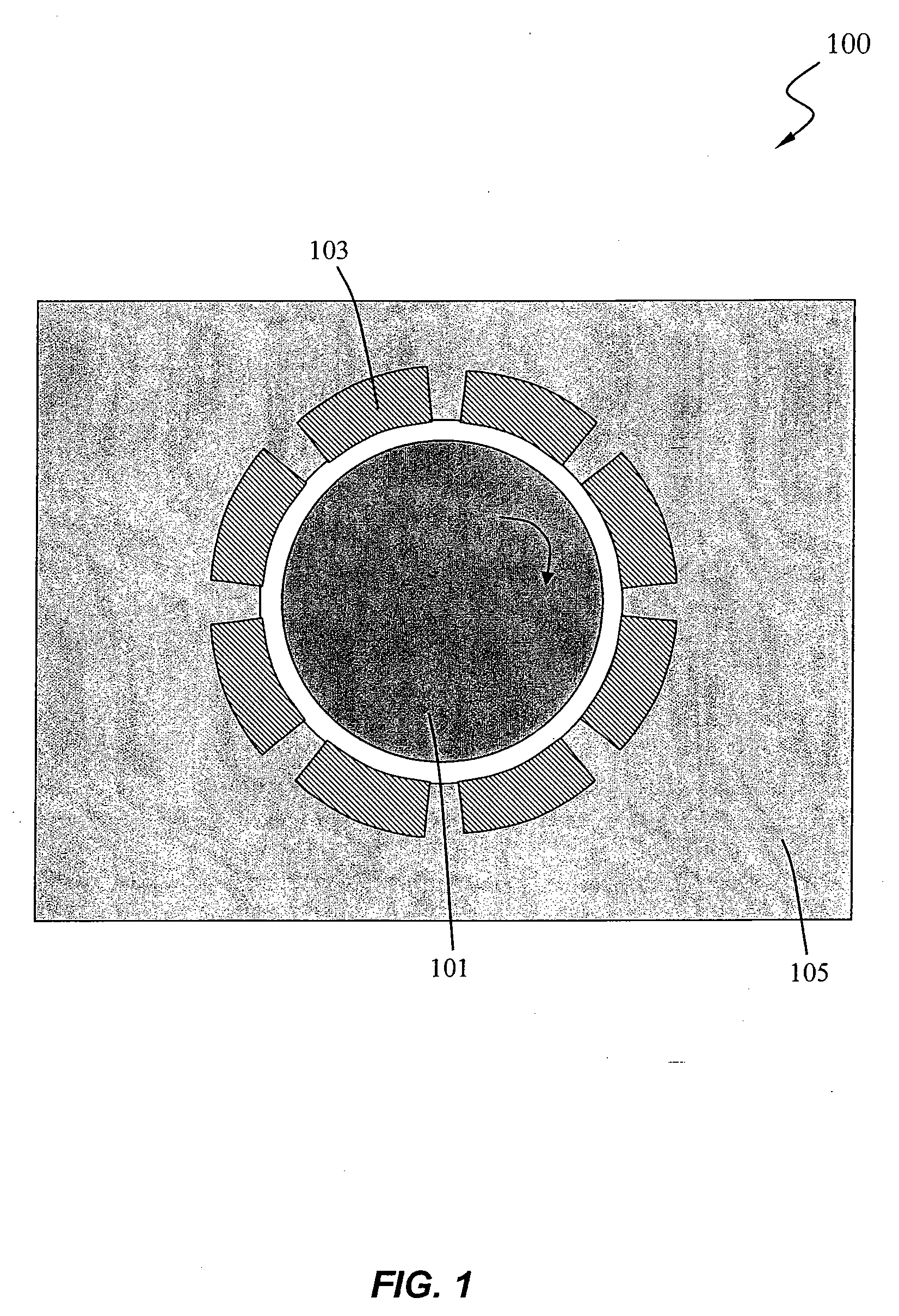
[0016]FIG. 1 is a simplified top-view diagram illustrating components of an integrated flywheel energy storage device according to one embodiment of the present invention. As illustrated, the integrated flywheel device is configured similar to an electrostatic micromotor. The flywheel 101 is actuated by the stator electrodes 103 and spins at high speed. With ac...


PUM


Abstract

The present invention relates to a method and device for fabricating an integrated flywheel device using semiconductor materials and IC/MEMS processes. Single crystal silicon has high energy storage/weight ratio and no defects. Single crystal silicon flywheel can operate at much higher speed than conventional flywheel. The integrated silicon flywheel is operated by electrostatic motor and supported by electrostatic bearings, which consume much less power than magnetic actuation in conventional flywheel energy storage systems. The silicon flywheel device is fabricated by IC and MEMS processes to achieve high device integration and low manufacturing cost. For the integrated silicon flywheel, high vacuum can be achieved using hermetic bonding methods such as eutectic, fusion, glass frit, SOG, anodic, covalent, etc. To achieve larger energy capacity, an array of silicon flywheels is fabricated on one substrate. Multiple layers of flywheel energy storage devices are stacked.

Description

CROSS-REFERENCES TO RELATED APPLICATIONS [0001] This application claims priority to provisional patent application Ser. No. 60 / 732,449; filed on Oct. 31, 2005; commonly assigned, and of which is hereby incorporated by reference for all purposes.BACKGROUND OF THE INVENTION [0002] A flywheel is an electromechanical battery that stores energy mechanically in the form of kinetic energy. Flywheels store energy very efficiently and energy density compared with chemical batteries. In addition to energy density, flywheel energy storage devices also offer several important advantages over chemical energy storage. The rate at which energy can be exchanged into or out of the battery is limited only by the motor-generator design. Therefore, it is possible to withdraw large amounts of energy in a far shorter time than with traditional chemical batteries. It is also possible to quickly charge flywheel devices. [0003] Flywheel energy storage devices are not affected by temperature changes as chemi...

Claims


Application Information

Patent Timeline
IPC IPC(8): H02K5/00H02K7/02H02K21/22
CPCH02K7/025H02N1/004H02N13/00Y02E60/16
Inventor YANG XIAO (CHARLES)
Owner YANG XIAO CHARLES
Why Eureka
Try Eureka