

Device for Catalytically Reducing Exhaust
a catalytic converter and converter technology, applied in the direction of machines/engines, lighting and heating apparatus, separation processes, etc., can solve the problems of increasing design time, cost, weight, and complexity of the exhaust system, and reducing the emissions of existing vehicles, so as to reduce the danger of exhaust gases and simplify the effect of cost and cos
- Summary
- Abstract
- Description
- Claims
- Application Information
AI Technical Summary
Benefits of technology
Problems solved by technology
Method used
Image

Examples
Embodiment Construction
[0033] Detailed descriptions of examples of the invention are provided herein. It is to be understood, however, that the present invention may be exemplified in various forms. Therefore, the specific details disclosed herein are not to be interpreted as limiting, but rather as a representative basis for teaching one skilled in the art how to employ the present invention in virtually any detailed system, structure, or manner.
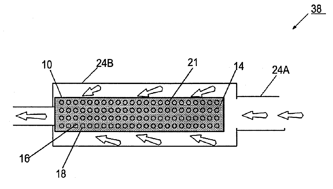
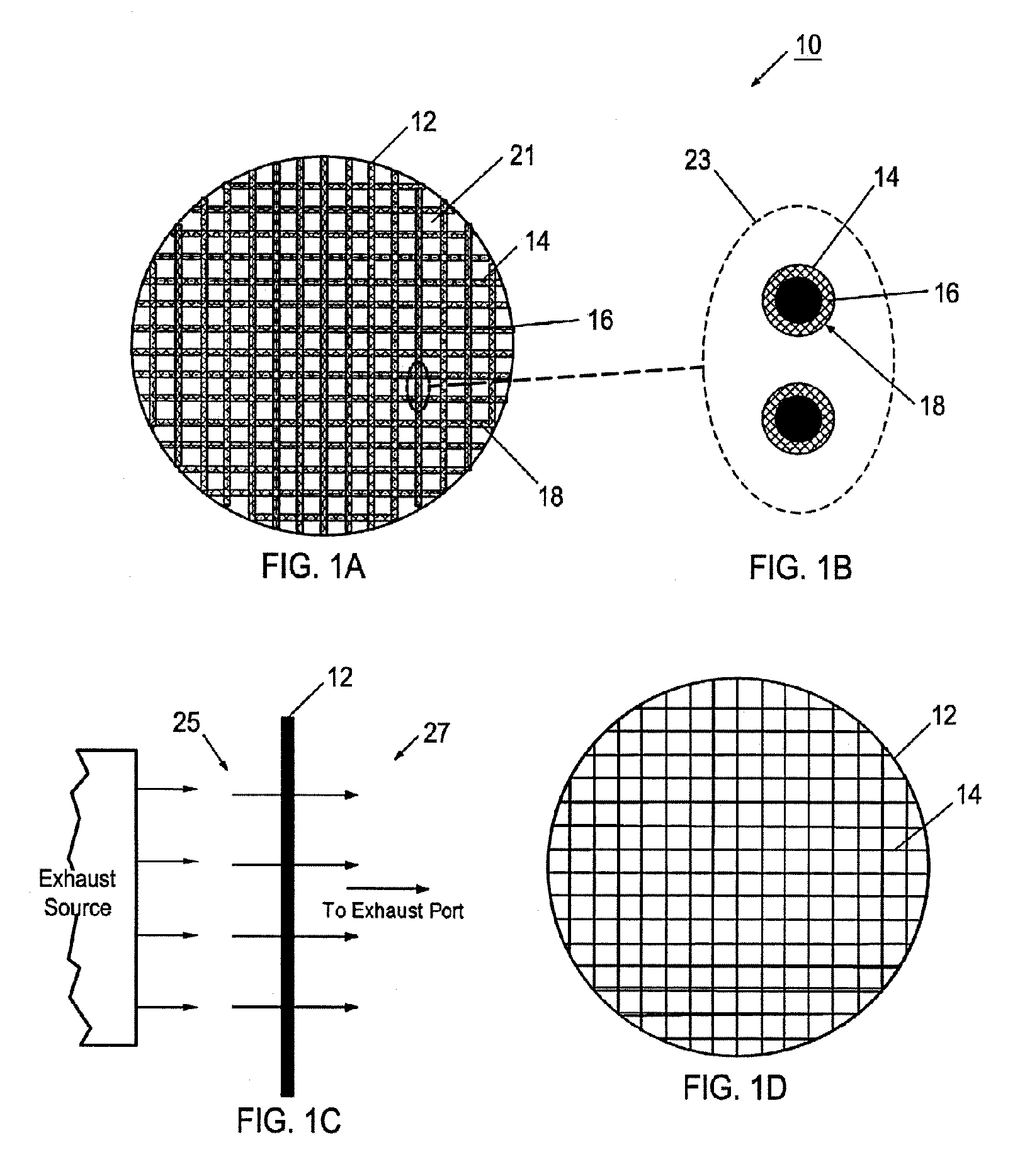
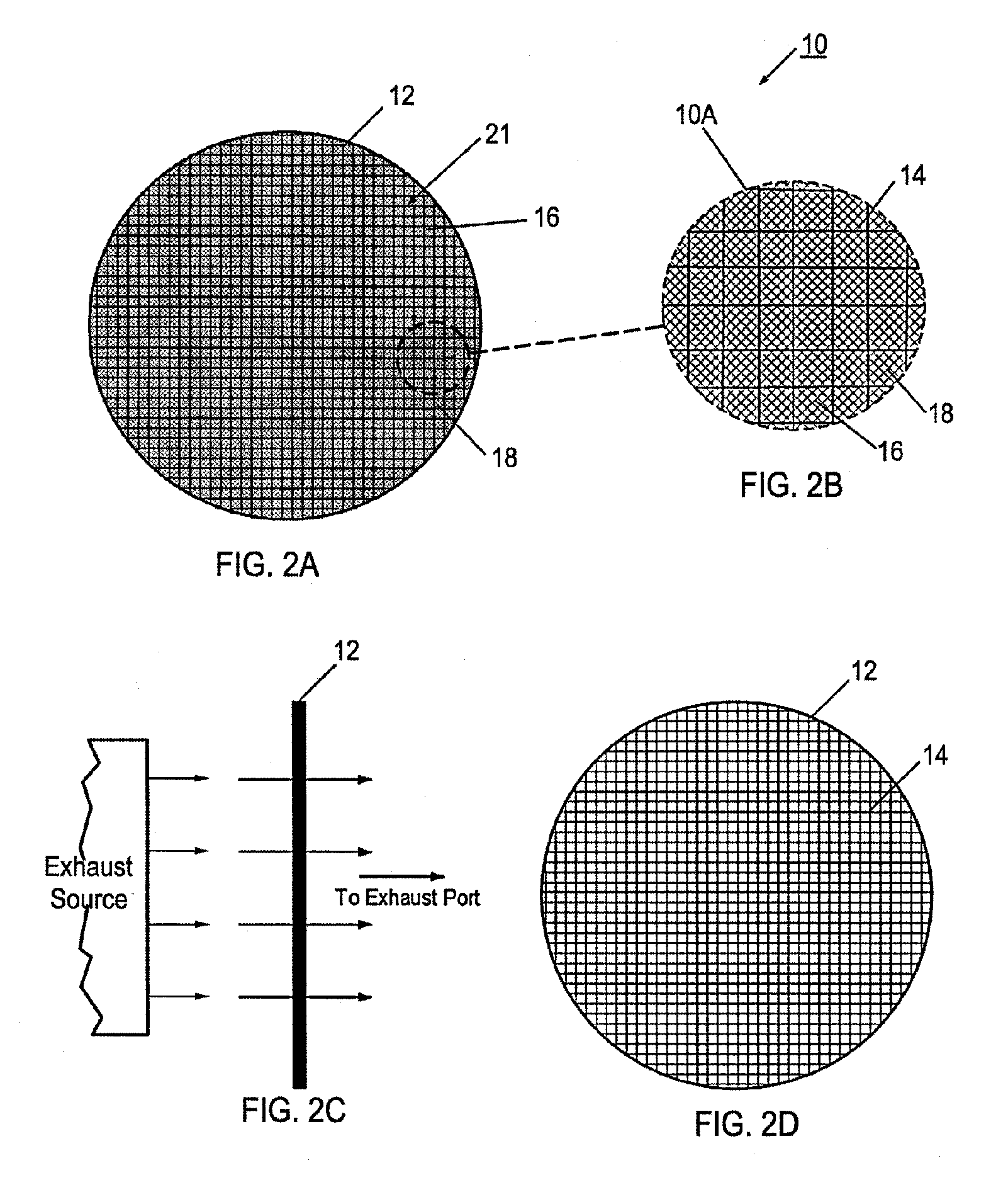
[0034] The drawing figures herein illustrate and refer to an exhaust system pathway that is specifically described as a component of an internal combustion engine exhaust system. However, it should be appreciated that exhaust pathway may be used on other types of exhaust systems. For example, the exhaust system may be for the petrochemical, biomedical, chemical processing, painting shops, laundromat, industrial exhaust, generation plant, or commercial kitchen applications.
[0035] Generally, a catalytic converting device consists of a host or a structural substra...
PUM
| Property | Measurement | Unit |
|---|---|---|
| effective diameter | aaaaa | aaaaa |
| diameters | aaaaa | aaaaa |
| length | aaaaa | aaaaa |
Abstract
Description
Claims
Application Information