Method and apparatus for a gas-liquid separator

a gas-liquid separator and separator technology, applied in the field of devices, can solve the problems of insufficient trapping, inconvenient operation, and the filter needs to be as small as possible, and achieve the effect of being convenient and efficien

Inactive Publication Date: 2007-05-17
GE02 TECH INC
View PDF39 Cites 24 Cited by
  • Summary
  • Abstract
  • Description
  • Claims
  • Application Information

AI Technical Summary

Benefits of technology

[0006] The present invention provides an inexpensive and efficient filter for the separation of gas and oil to trap and coalesce liquid and particulate matter in a fluid stream. The filter of the present invention is composed of bonded fibers in a porous ceramic substrate housed within a housing. The housing provides an inlet for a mixture of gas and liquid, and an outlet for the gas that has been filtered by the porous ceramic substrate. A liquid collection area receives the liquid that has been coalesced from within the porous substrate. In an embodiment of the invention, the porous substrate has channels that form a honeycomb configuration. The honeycomb substrate can be provided in a wall-flow configuration with a set of inlet channels and outlet channels arranged in an alternating pattern.
[0007] In a more specific example, the air-oil separator of the present invention is used in a crank case ventilation system. In this embodiment, the porous ceramic substrate is mounted in a housing that is connected to a crank case vent on an engine. The system has an inlet connecting the crank case vent to the filter with an exhaust line for the filtered vent gas and an oil return line for the oil that has been coalesced and collected by the filter. In another embodiment, a second stage filter can be used to collect coalesced oil droplets that pass through the filter into the exhaust stream. These escaped particles can be easily trapped and collected by conventional pleated paper, or fiberglass filters.

Problems solved by technology

Second, the filter needs to be as small as possible, as space is at a premium in the design of current engine systems.
However, these design considerations are in conflict.
For example, a filter system which removes a large quantity of oil and particulate may have to be large (in order to last a long enough period before needing a replacement or regeneration) , or if the filter is made compact, it may generate an unacceptable back pressure to the engine or may not trap sufficiently.
Such a filter is quite coarse, and relatively ineffective for removal of oil or particulate matter.
Due to the ineffectiveness of such mesh filters, newer filters have been developed using a fiberglass filter.
However, these nano-fiber filters are typically expensive, present a risk of secondary emissions of nanofiber particles, and produce higher backpressures.
Consequently, standard fiberglass filters (wrapped or pleated paper honeycomb) must be relatively large to adequately filter exhaust gas, and are subject to easy clogging and high backpressures.
Developments are occurring in the field of new fiber chemistries and fiber diameters, in order to better trap and coalesce the liquid media in a fluid stream, but the basic geometry, form, and structure of the filters remains a problem.
However, none of the fibrous systems in the mat, i.e., paper wrapped around a central spindle, or pleated in the form of a honeycomb, or pleated in the form of a donut design, have provided adequate filtration in the desired filter size range.
However, the electrostatic precipitator is very expensive, and requires external power and external control systems, complicating the integration of electrostatic precipitator into existing engine systems.
Other exotic systems, such as centrifuge systems, may also be used in highly specialized applications, but do not provide cost-effective filtration for mass production.
Accordingly, all known technologies suffer either from inadequate filtration, excessive back pressure, excessive size, or excessive of cost.

Method used


Image

  • Method and apparatus for a gas-liquid separator
  • Method and apparatus for a gas-liquid separator
  • Method and apparatus for a gas-liquid separator

Examples


Embodiment Construction

[0022] Detailed descriptions of examples of the invention are provided herein. It is to be understood, however, that the present invention may be exemplified in various forms. Therefore, the specific details disclosed herein are not to be interpreted as limiting, but rather as a representative basis for teaching one skilled in the art how to employ the present invention in virtually any detailed system, structure, or manner.

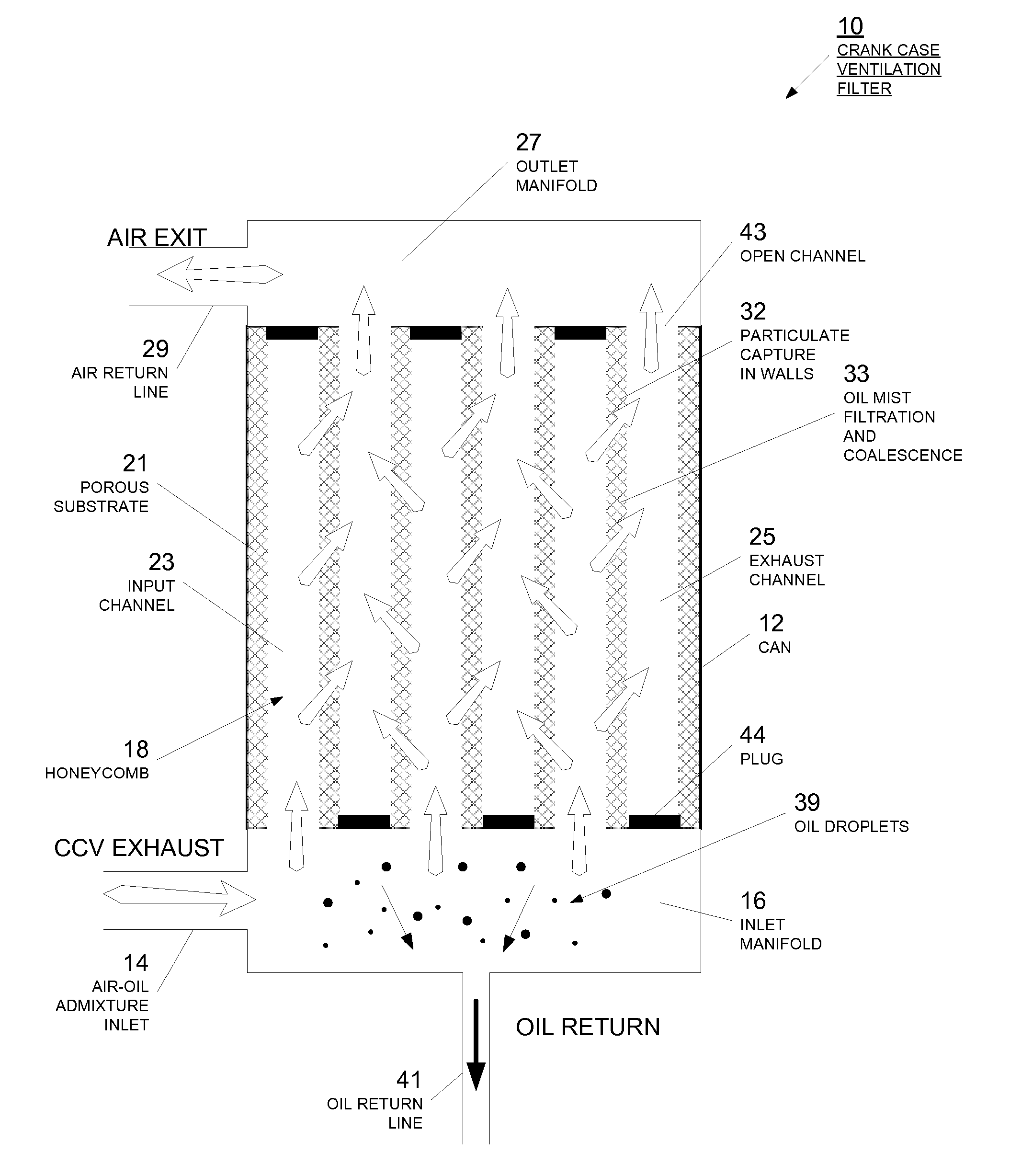
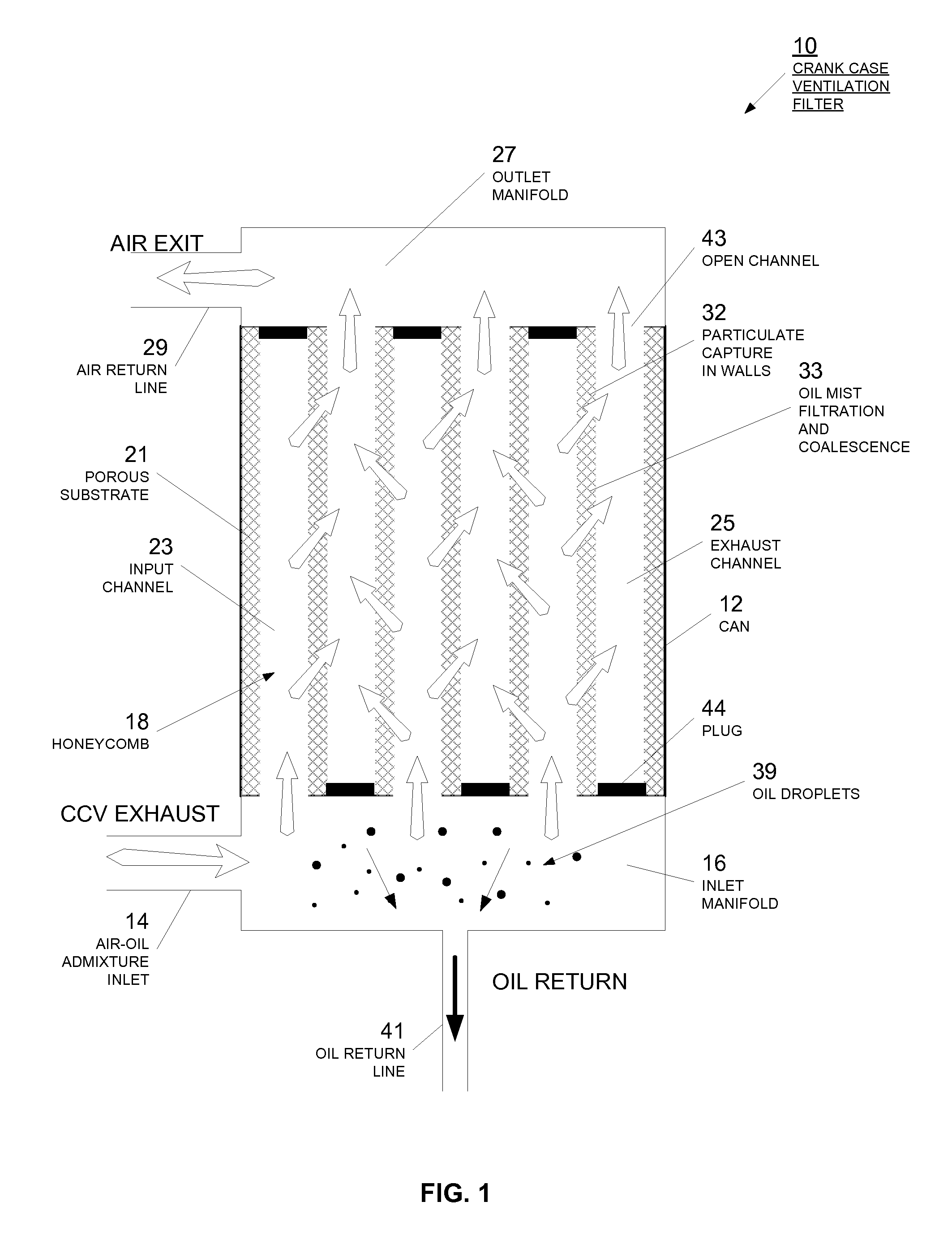
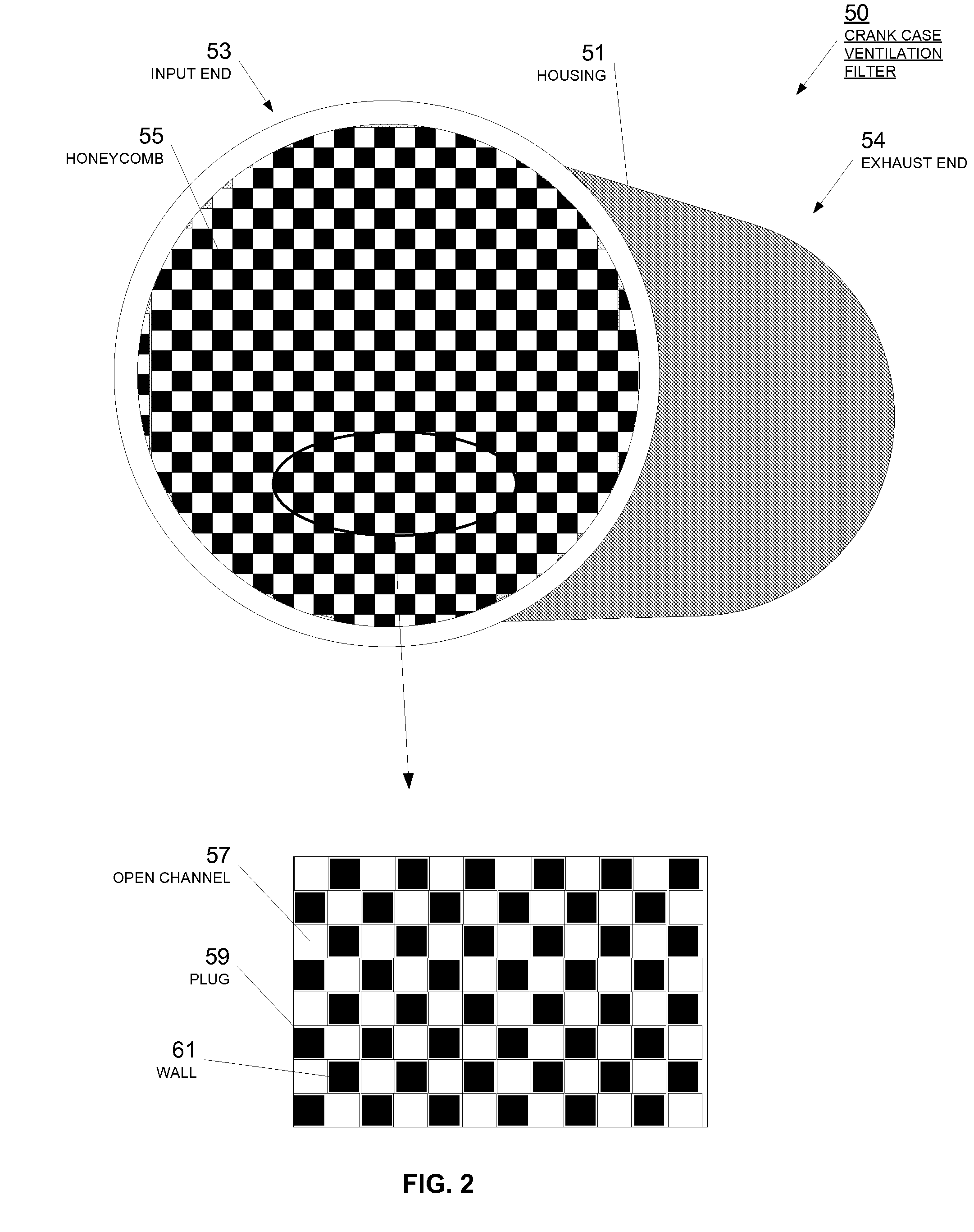
[0023] Referring now to FIG. 1, a gas-liquid filter is illustrated. The gas-liquid filter is illustrated as a crank case ventilation filter 10 for separating oil from a gas exhausted from the crank case of an engine. One skilled in the art will appreciate that while the illustrative embodiment of FIG. 1 is directed toward a crank case ventilation of an internal combustion engine, such as a diesel or gasoline engine, the filter 10 can be used for a variety of gas-liquid separation applications, such as, for example, in an air compressor. Crank case ventilation fi...


PUM

PropertyMeasurementUnit
porosityaaaaaaaaaa
diameteraaaaaaaaaa
diameteraaaaaaaaaa

Abstract

A porous ceramic substrate is provided for coalescing and trapping particulate, including liquid, in a gas stream. The porous ceramic substrate is composed essentially of fibrous ceramic material, with bonded fibers that create a network of interconnected pores. A variety of fibers can be used, with a range of fiber diameters, to provide efficient coalescing of particulates in a gas stream. Oil droplets are trapped and coalesced by the porous ceramic substrate, that are collected and thus, separated from the gas stream. Filtered gas is directed out of the filter, while the collected particulates are received in a collection area. The porous ceramic substrate composed of essentially fibrous ceramic material can be configured in a honeycomb configuration with channels that provide an inlet channel and / or an outlet channel. Wall flow configurations can be provided to direct the flow of the gas stream through the porous ceramic material from an inlet channel into an outlet channel.

Description

RELATED APPLICATIONS [0001] This application is a continuation-in-part of U.S. patent application Ser. No. 11 / 322,777, filed Dec. 30, 2005, entitled “Process for Extruding a Porous Substrate”, which claims priority to U.S. provisional patent application Ser. No. 60 / 737,237, filed Nov. 16, 2005, and entitled “System for Extruding a Porous Substrate”; both of which are incorporated by reference herein in their entirety.BACKGROUND [0002] The present invention relates generally to a device for separating a liquid from a gas, and in one example, to an air-oil separator using a ceramic honeycomb structure for effecting the separation. DESCRIPTION OF RELATED ART [0003] A liquid-gas separator is used in many industrial, commercial, and residential applications. Other applications may exist in other fields such as in military applications. A liquid gas separator is typically attached to an exhaust line for removing a liquid content from a gas. In one particular example, a gas liquid separato...

Claims


Application Information

Patent Timeline
Patent Type & Authority Applications(United States)
IPC IPC(8): B01D39/20B01D50/00B01D53/34
CPCB01D39/2086B01D39/2089B01D46/0031B01D46/006B01D46/2429B01D2046/2433B01D2257/7022B01D2279/30F02M25/06B01D46/24491B01D46/80
Inventor ZUBERI, BILAL
Owner GE02 TECH INC
Why Eureka
Try Eureka