Air power energy transformation to electrical energy for hybrid electric vehicle applications

Inactive Publication Date: 2007-05-17
INT TRUCK INTPROP LLC
View PDF24 Cites 34 Cited by
  • Summary
  • Abstract
  • Description
  • Claims
  • Application Information

AI Technical Summary

Benefits of technology

[0006] There exists an area of air movement relative to a moving vehicle that heretofore remains unexploited as a source of energy, and which presents the possibility of extracting energy from said air movement without requiring additional energy in order to move the vehicle. To an even greater degree of benefit, extracting energy from this area of air movement may even decrease the amount of energy required to move the vehicle. That area of air movement is the area of recirculation in between the segments of an articulated vehicle combination, or in the aerodynamic wake behind the vehicle.
[0007] Articulated moving vehicles, such as highway tractor and semi-trailer combinations, possess a large gap between the tractor and trailer due to constraints having to do with articulation at low speeds. At high speeds, air passing over and around the vehicle recirculates within this gap. As a moving fluid exerts less pressure and as a greater velocity of relative movement occurs near the rear side of the tractor cab due to this recirculation, the net pressure differential between the forward side of the tractor portion of the vehicle and the rearward side of the tractor portion of the vehicle is increased as a result of this recirculation. Extra

Problems solved by technology

Because these turbines, or the ducts leading to them, were continually in the vehicle slipstream, they caused a net increase in the amount of power required to drive the vehicle to overcome air resistance.
These vehicles, typically passenger vehicles and delivery vehicles, use large amounts of energy accelerating and accumulating kinetic energy, which is then lost upon braking.
Articulated moving vehicles, such as highway tractor and semi-trailer combi

Method used


Image

  • Air power energy transformation to electrical energy for hybrid electric vehicle applications
  • Air power energy transformation to electrical energy for hybrid electric vehicle applications
  • Air power energy transformation to electrical energy for hybrid electric vehicle applications

Examples


Example

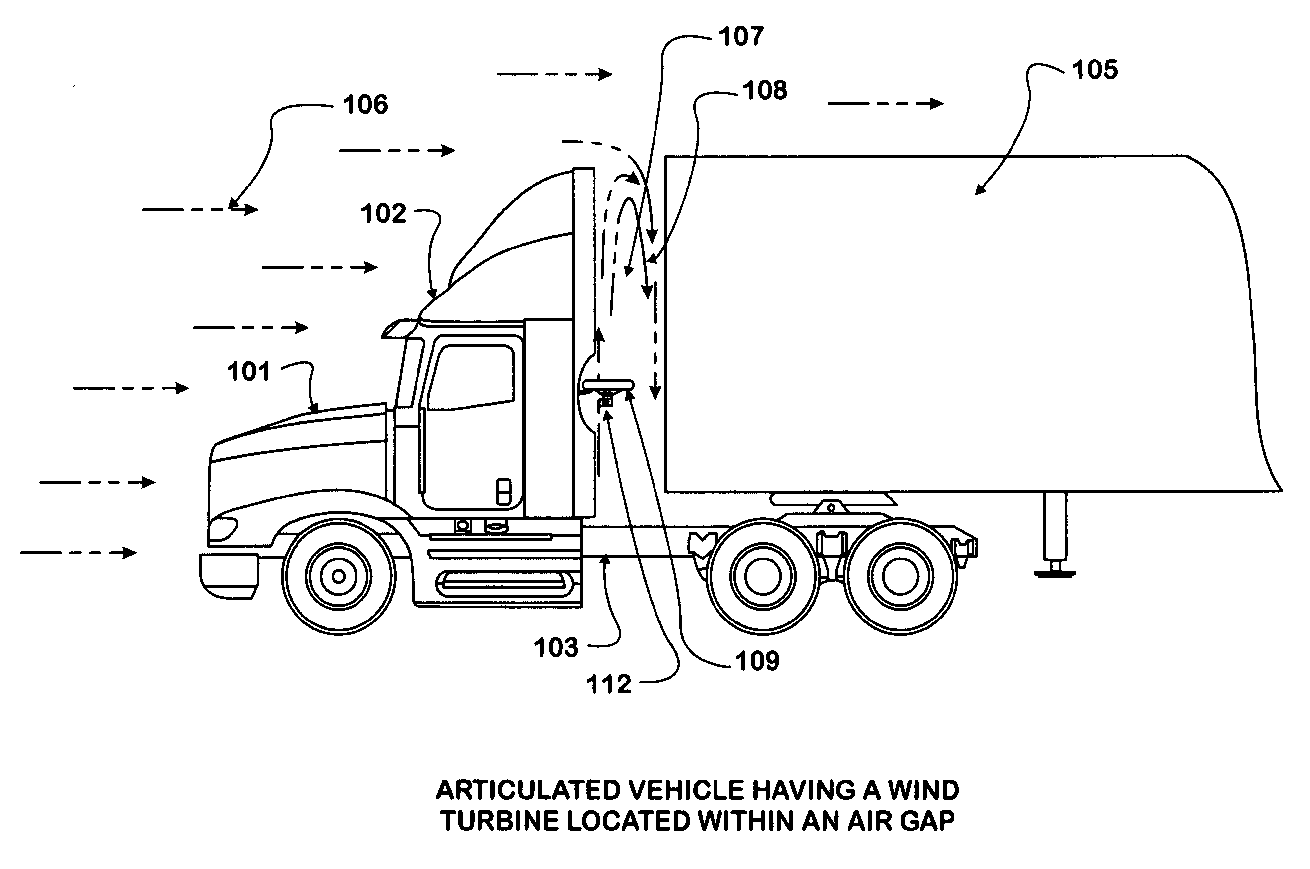
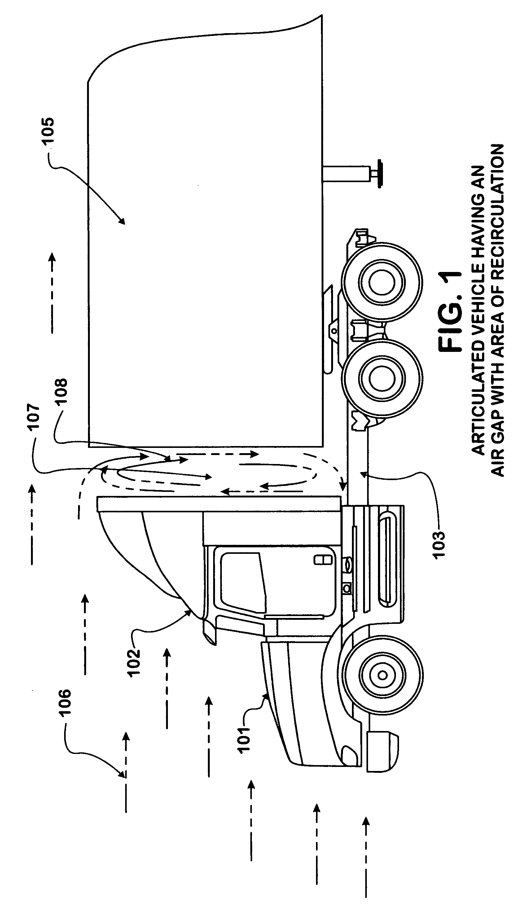
[0021] The vehicle 101 shown in FIG. 1 has a cab 102 attached to a chassis 103, and is adapted to pull a semi-trailer 105, which semi-trailer 105 is partially shown. FIG. 1 further shows airflow 106 relative to the moving vehicle 101. Located between the cab 102 of the vehicle 101 and the semi-trailer 105 attached to the vehicle 101, is a vehicle gap 107, within which exists an area of air recirculation 108.

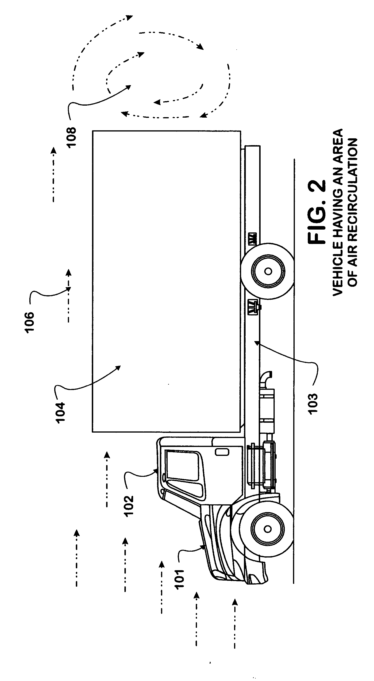
[0022] The vehicle 101 shown in FIG. 2 has a cab 102 attached to a chassis 103, and is provided with a cargo-carrying body section 104. Airflow 106 is shown relative to the moving vehicle 101, behind which vehicle 101 exists an area of recirculation 108.

[0023]FIG. 3 shows a wind turbine 109 having turbine blades 110 coupled to a generator 112 by means of a shaft 113. The wind turbine 109 may be provided with a turbine housing 111, within which the turbine blades 110 rotate. The wind turbine 109 is supported by a turbine mounting 115. The generator 112 provides electrical power ...


PUM


Abstract

A vehicle having one or more small vehicle-mounted electricity generating wind turbines located within an area of wind recirculation. The electricity generated is used to recharge vehicle batteries, partially power an auxiliary electric propulsion motor, or supply vehicle parasitic loads.

Description

BACKGROUND OF INVENTION [0001] This invention relates to the use of one or more small vehicle-mounted wind turbines connected to one or more small generators to generate electricity for use by a vehicle when in motion. Specifically, the wind turbines are located in an area of wind recirculation in between the segments of an articulated vehicle combination, or in the aerodynamic wake behind the vehicle. SUMMARY [0002] With the advent of modern Hybrid Electric Vehicles, much development has occurred in the art having to do with recapturing vehicle kinetic energy and regeneration of that energy into a useable form. The primary focus of development has been in the area of regenerative vehicle braking. Other areas of development have focused upon utilizing secondary sources of available energy, such as solar energy or wind energy. [0003] In many prior-art developments concerning the use of wind energy to provide power to Hybrid Electric Vehicles, the inventions as set forth have consumed...

Claims


Application Information

Patent Timeline
IPC IPC(8): B60K16/00
CPCB60K16/00B60K2016/006F03D9/002F05B2240/941Y02T10/7083Y02T10/90Y02E10/725B60L8/006F03D9/25Y02E10/728F03D3/04F03D9/32Y02E10/72Y02T10/7072
Inventor BRADLEY, JAMES C.JAIN, SUNIL K.KLINGER, RODNEY J.PENALOZA, JOSEPH T.
Owner INT TRUCK INTPROP LLC
Why Eureka
Try Eureka