Medical implant deployment tool

a technology for medical implants and deployment tools, which is applied in the field of system for the delivery and deployment of a replacement heart valve, can solve the problems of bleeding, heart attack, stroke, and adverse reactions to anesthesia medications, and achieve the effect of safe delivery of the proper for

Active Publication Date: 2007-05-17
BOSTON SCI SCIMED INC
View PDF116 Cites 364 Cited by
  • Summary
  • Abstract
  • Description
  • Claims
  • Application Information

AI Technical Summary

Benefits of technology

[0019] It is another objective of the present invention to provide a system able to exert the needed actuation forces for both deployment, and redeployment of the replacement heart valve.
[0020] Yet another objective is to provide for a deployment system having a reliable actuator system for safely delivering the proper level of forces to the implant and the deployment mechanism that the implant requires.

Problems solved by technology

Valve replacement surgery is a highly invasive operation with significant concomitant risk.
Risks include bleeding, infection, stroke, heart attack, arrhythmia, renal failure, adverse reactions to the anesthesia medications, as well as sudden death.
PVT's device suffers from several drawbacks.
Deployment of PVT's stent is not reversible, and the stent is not retrievable.
This is a critical drawback because improper positioning too far up towards the aorta risks blocking the coronary ostia of the patient.
Furthermore, a misplaced stent / valve in the other direction (away from the aorta, closer to the ventricle) will impinge on the mitral apparatus and eventually wear through the leaflet as the leaflet continously rubs against the edge of the stent / valve.
Another drawback of the PVT device is its relatively large cross-sectional delivery profile.
The PVT system's stent / valve combination is mounted onto a delivery balloon, making retrograde delivery through the aorta challenging.
An antegrade transseptal approach may therefore be needed, requiring puncture of the septum and routing through the mitral valve, which significantly increases complexity and risk of the procedure.
Very few cardiologists are currently trained in performing a transseptal puncture, which is a challenging procedure by itself
Standard self-expanding systems have very poor accuracy in deployment, however.
It is therefore often impossible to know where the ends of the stent will be with respect to the native valve, the coronary ostia and the mitral valve.
Visulization prior to final and irreversible deployment cannot be done with standard self-expanding systems, however, and the replacement valve is often not fully functional before final deployment.
Another drawback of prior art self-expanding replacement heart valve systems is their lack of radial strength.
However when the stent has a valve fastened inside it, as is the case in aortic valve replacement, the anchoring of the stent to vessel walls is significantly challenged during diastole.
Moreover, a self-expanding stent without sufficient radial force will end up dilating and contracting with each heartbeat, thereby distorting the valve, affecting its function and possibly migrating and dislodging completely.
Simply increasing strut thickness of the self-expanding stent is not a practical solution as it runs the risk of larger profile and / or plastic deformation of the self-expanding stent.
While providing for an aortic approach, devices described in the Garrison patent application suffer from several drawbacks.
First, the stent portion of the device is delivered across the native valve as a single piece in a single step, which precludes dynamic repositioning of the stent during delivery.
Stent foreshortening or migration during expansion may lead to improper alignment.
This increases an immediate risk of blocking the coronary ostia, as well as a longer-term risk of migration of the device post-implantation.
Tissue may protrude through these gaps, thereby increasing a risk of improper seating of the valve within the stent.
However deploying and redeploying the heart valve is not without its own set of technical challenges.
One challenge with using mechanical elements to connect the user control with an implantable device and / or its delivery system is assuring that the user controls properly actuate the mechanical components of the system, particularly when the deployment tool or catheter navigates the tortuous path from its insertion point to the deployment location, such as the heart.
If differences in actuator path lengths are not properly compensated for, the operation of the deployment tool may not be predictable.
In either scenario, the operation and deployment become unpredictable and unreliable.
If stresses on the actuation elements are too great, they may cause deformation or distortion of the implant before any of the actuation elements are even used.
This could result in serious complications that may require invasive procedures to intervene.

Method used


Image

  • Medical implant deployment tool
  • Medical implant deployment tool
  • Medical implant deployment tool

Examples


Embodiment Construction

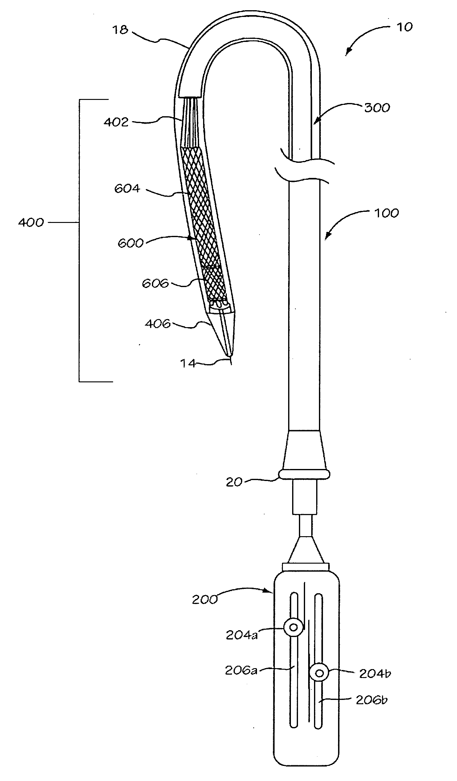
[0040] The invention is drawn to methods, mechanisms and tools for the endovascular deployment of medical implants, such as replacement heart valves. According to some embodiments of the invention, the deployment process includes actuating one or more actuation elements to control and / or perform actions of the implant deployment mechanism, or mechanical elements of the implant itself. The operation of the implant deployment mechanism or the mechanical elements of the implant are often fully reversible, allowing a physician to partially deploy and then reverse the deployment operation of (“undeploy”) the implant. This provides the ability to reposition and redeploy the implant. As a general reference, the orientation of the system is referred to as is traditional for a medical device catheter. The proximal end is nearest the physician or operator when the system is being used. The distal end is furthest away from the operator and is in the patient's vasculature. To facilitate imaging...


PUM


Abstract

A medical implant deployment tool and deployment method are disclosed. One aspect of the invention provides an implant system including an implant adapted for endovascular delivery and deployment; and a deployment tool adapted to deploy the implant, with the deployment tool having an actuation controller; a plurality of actuation elements adapted to apply forces to one or more implant deployment mechanisms and each adapted to extend along an actuation element path within a patient's vasculature; and an actuation element compensation mechanism adapted to compensate for differences in length between the actuation element paths. Another aspect of the invention provides a method of deploying an implant including the steps of endovascularly delivering an implant and implant deployment mechanisms to an implant site and applying an actuation force to the implant deployment mechanisms through actuation elements extending through the patient's vasculature while compensating for differences in length between actuation element path lengths to deploy the implant.

Description

BACKGROUND OF THE INVENTION [0001] The present invention relates principally to a system for the delivery and deployment of a replacement heart valve. Heart valve surgery is used to repair or replace diseased heart valves. Valve surgery is an open-heart procedure conducted under general anesthesia. An incision is made through the patient's sternum (sternotomy), and the patient's heart is stopped while blood flow is rerouted through a heart-lung bypass machine. [0002] Valve replacement may be indicated when there is a narrowing of the native heart valve, commonly referred to as stenosis, or when the native valve leaks or regurgitates. When replacing the valve, the native valve is excised and replaced with either a biologic or a mechanical valve. Mechanical valves require lifelong anticoagulant medication on to prevent blood clot formation, and clicking of the valve often may be heard through the chest. Biologic tissue valves typically do not require such medication. Tissue valves may...

Claims


Application Information

Patent Timeline
Patent Type & Authority Applications(United States)
IPC IPC(8): A61B17/94A61F2/84
CPCA61F2/2418A61F2/2439A61M25/0136A61F2230/0054A61M25/0147A61F2002/9517A61M25/0144A61F2/9517
Inventor SALAHIEH, AMRHAUG, ULRICH R.ARGENTO, CLAUDIOMOREJOHN, DWIGHTHILDEBRAND, DANIELSAUL, TOM
Owner BOSTON SCI SCIMED INC
Why Eureka
Try Eureka