Optical filter

a technology of optical filters and crystal plates, applied in the field of optical filters, can solve the problem of difficult to obtain crystal plates of this thickness, and achieve the effects of improving the strength and rigidity of the optically, reducing the difficulty of optically bending, and improving the performance of the optically

Inactive Publication Date: 2007-05-31
DAISHINKU CORP
View PDF4 Cites 4 Cited by
  • Summary
  • Abstract
  • Description
  • Claims
  • Application Information

AI Technical Summary

Benefits of technology

[0022] With the optical filter according to the present invention, at least one optically anisotropic crystal plate and at least one substrate are stuck together in a state in which a principal face of the optically anisotropic crystal plate and a principal face of the substrate are perpendicular to the direction of transmission of the ray, and the optically anisotropic crystal plate or the substrate is used as the end face on the ray incident side, and another optically anisotropic crystal plate or another substrate that is thinner than the optically anisotropic crystal plate or the substrate that is the end face on the ray incident side is stuck onto said optically anisotropic crystal plate or said substrate, so there is less warping or distortion of the optically anisotropic crystal plate due to external factors such as the effect of heat, an optical coating, or an adhesive, and warping or distortion caused by internal factors of the optically anisotropic crystal plate itself, occurring due to variance in polishing precision or the like, is also corrected, affording better parallelism and flatness of the principal faces of the optical filter. In other words, the angle of incidence of a ray incident on one of the principal faces of the optical filter (and particularly the end face on the incident side) will not be changed by warping or distortion. Accordingly, the desired phase characteristics and double refraction characteristics are obtained, and there is no adverse effect on optical characteristics. Also, since warping or distortion will have no effect even if the optically anisotropic crystal plate is made thinner, higher performance can be achieved. Also, since warping or distortion will have no effect even if the optically anisotropic crystal plate is made thinner, higher performance can be achieved.
[0023] Also, with the optical filter according to the present invention, at least one optically anisotropic crystal plate and at least one substrate are stuck together in a state in which a principal face of the optically anisotropic crystal plate and a principal face of the substrate are perpendicular to the direction of transmission of the ray, and the optically anisotropic crystal plate or the substrate is used as the end face on the ray exit side, and another optically anisotropic crystal plate or another substrate that is thinner than the optically anisotropic crystal plate or the substrate that is the end face on the ray exit side is stuck onto said optically anisotropic crystal plate or said substrate, so there is less warping or distortion of the optically anisotropic crystal plate due to external factors such as the effect of heat, an optical coating, or an adhesive, and warping or distortion caused by internal factors of the optically anisotropic crystal plate itself, occurring due to variance in polishing precision or the like, is also corrected, affording better parallelism and flatness of the principal faces of the optical filter.
[0024] An even more favorable effect will be realized by combining the above constitutions of the present invention.
[0025] Also, if thick substrates are applied so as to sandwich the principal faces at both ends of the optically anisotropic crystal substrate, not only will this increase the strength and rigidity of the optically anisotropic crystal substrate, but there will be no scratching of the principal faces of the optically anisotropic crystal substrate by external factors, or cracking and chipping of the optically anisotropic crystal plate. In particular, making an optically anisotropic crystal plate thinner can result in inadequate strength or rigidity, making the above damage even more pronounced, but the above constitution prevents this.
[0026] In addition to the effects described above, if a glass substrate is used, then this substrate will have no adverse effect on the phase characteristics or double refraction characteristics obtained with the optically anisotropic crystal plate. Also, since the coefficient of thermal expansion approximates that of the optically anisotropic crystal plate, no warping or distortion will occur in the optically anisotropic crystal plate as a result of a thermal effect, and a less expensive substrate can be obtained.
[0027] In addition to the effects described above, in the formation of an optical coating by vacuum vapor deposition, sputtering, or another such method, an optical coating can be formed on the substrate, which is relatively thick and unaffected by warping, distortion, or the like, rather than forming an optical coating on the optically anisotropic crystal plate, which is relatively thin and more readily affected by warping, distortion, or the like, so an optical filter can be provided without damage caused by distortion of the optically anisotropic crystal plate.

Problems solved by technology

However, difficulties in machining crystals make it hard to obtain a crystal plate of this thickness.

Method used


Image

  • Optical filter
  • Optical filter
  • Optical filter

Examples


first embodiment

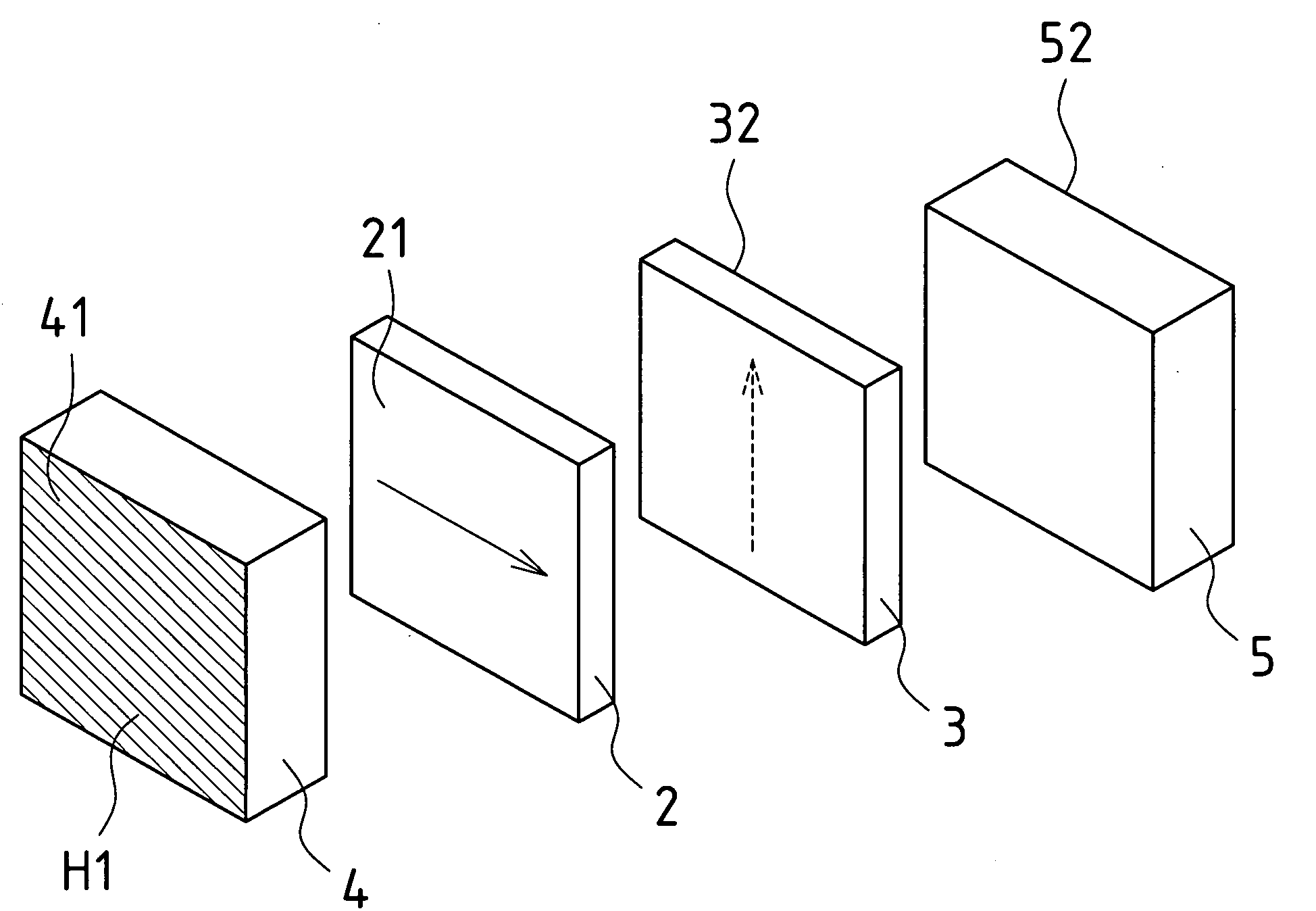
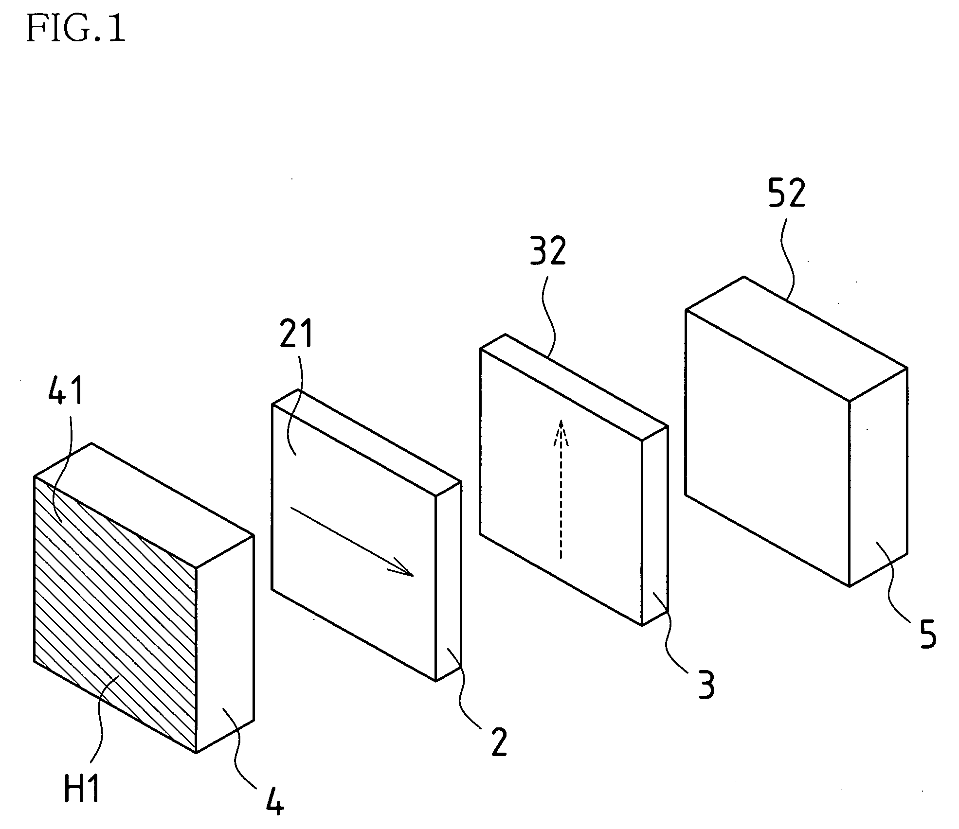
[0049] A first embodiment of the present invention will now be described, using a phase plate as an example, through reference to the drawings. FIG. 1 is an exploded perspective view of the phase plate according to this embodiment, FIG. 2 is a perspective view of the assembled state in FIG. 1, and FIG. 3 is a side view of FIG. 2.

[0050] As shown in these drawings, an optical filter 1 is constituted by two crystal plates (optically anisotropic crystal plates) 2 and 3, and glass substrates 4 and 5. This will now be described in more specific terms. Here, the front side in FIGS. 1 and 2 (the left side in FIG. 3) shall be the incident face (referred to as the incident side end face in the present invention), the crystal plate that is in the front is called a first crystal plate 2, the glass substrate that is in the front is called a first glass substrate 4, the back side (the right side in FIG. 3) shall be the exit face (referred to as the exit side end face in the present invention), t...

second embodiment

[0056] A second embodiment of the present invention will now be described, using an optical low pass filter as an example, through reference to the drawings. FIG. 4 is an exploded perspective view of the optical low pass filter according to this embodiment, FIG. 5 is a perspective view of the assembled state in FIG. 4, and FIG. 6 is a side view of FIG. 5.

[0057] As shown in these drawings, an optical low pass filter 6 is constituted by a crystal plate (optically anisotropic crystal plate) 7 and glass substrates 8 and 9. This will now be described in more specific terms. Here, the front side in FIGS. 4 and 5 (the left side in FIG. 6) shall be the incident face (referred to as the incident side end face in the present invention), the glass substrate that is in the front is called a first glass substrate, the back side (the right side in FIG. 6) shall be the exit face (referred to as the exit side end face in the present invention), and the glass substrate that is in the back is called...

working example 1

[0064] As shown in FIG. 7, the optical filter 6 according to this Working Example 1 includes the crystal plate A, the substrate C, the crystal plate B, the crystal plate D, and the substrate E stuck together, in that order from the left in the drawing, with a UV adhesive S6. The crystal plate A, the substrate C, the crystal plate B, the crystal plate D, and the substrate E here are disposed in an overlapping state. An antireflective film (optical coating) is formed on the exit side end face Al of the crystal plate A, which corresponds to one side face of the optical filter 6. An infrared-cut coating (optical coating) is formed on the incident side end face E1 of the substrate E, which corresponds to the other side face of the optical filter 6.

[0065] With the optical filter 6 according to this Working Example 1, starting from the left side in FIG. 6, the thickness of the crystal plate A is set to 260 μm, the thickness of the substrate C is set to 1200 μm, the thickness of the crysta...


PUM

PropertyMeasurementUnit
thicknessaaaaaaaaaa
thicknessaaaaaaaaaa
thicknessaaaaaaaaaa

Abstract

This optical filter is constituted such that at least one optically anisotropic crystal plate and at least one substrate are stuck together in a state in which a principal face of the optically anisotropic crystal plate and a principal face of the substrate are perpendicular to the direction of transmission of the ray. Also, a substrate is used as the end face on the ray incident side, and another optically anisotropic crystal plate or another substrate that is thinner than the substrate that is the end face on the ray incident side is stuck onto the substrate.

Description

TECHNICAL FIELD [0001] The present invention relates to an optical filter such as a phase plate or an optical low pass filter used in any of a variety of optical devices. BACKGROUND ART [0002] Phase plates and optical low pass filters (crystal double refraction plates) have been used in the past in various optical devices as optical filters that change the optical characteristics of a ray transmitted by a crystal or other such optically anisotropic crystal plate. Of these, the phase plates are suited to polarizing optical systems such as liquid crystal projectors or pickups for optical disks, and are elements that get a phase between an ordinary ray and an extraordinary ray by utilizing a speed difference between the two rays in a crystal or other such optically anisotropic medium. When this is configured as a quarter-wave plate (the phase is configured at π / 2), linearly polarized light is converted into circularly polarized light, or circularly polarized light is converted into lin...

Claims


Application Information

Patent Timeline
Patent Type & Authority Applications(United States)
IPC IPC(8): G02F1/1335G02B5/30
CPCG02B27/46G02B5/3083
Inventor SHOGAKI, TATSUYAMATSUI, HIROAKI
Owner DAISHINKU CORP
Why Eureka
Try Eureka