
Handheld tape applicator and components thereof, and their methods of use

Inactive Publication Date: 2007-06-07
HUBER ENGINEERED WOODS
View PDF26 Cites 29 Cited by
  • Summary
  • Abstract
  • Description
  • Claims
  • Application Information

AI Technical Summary

Benefits of technology

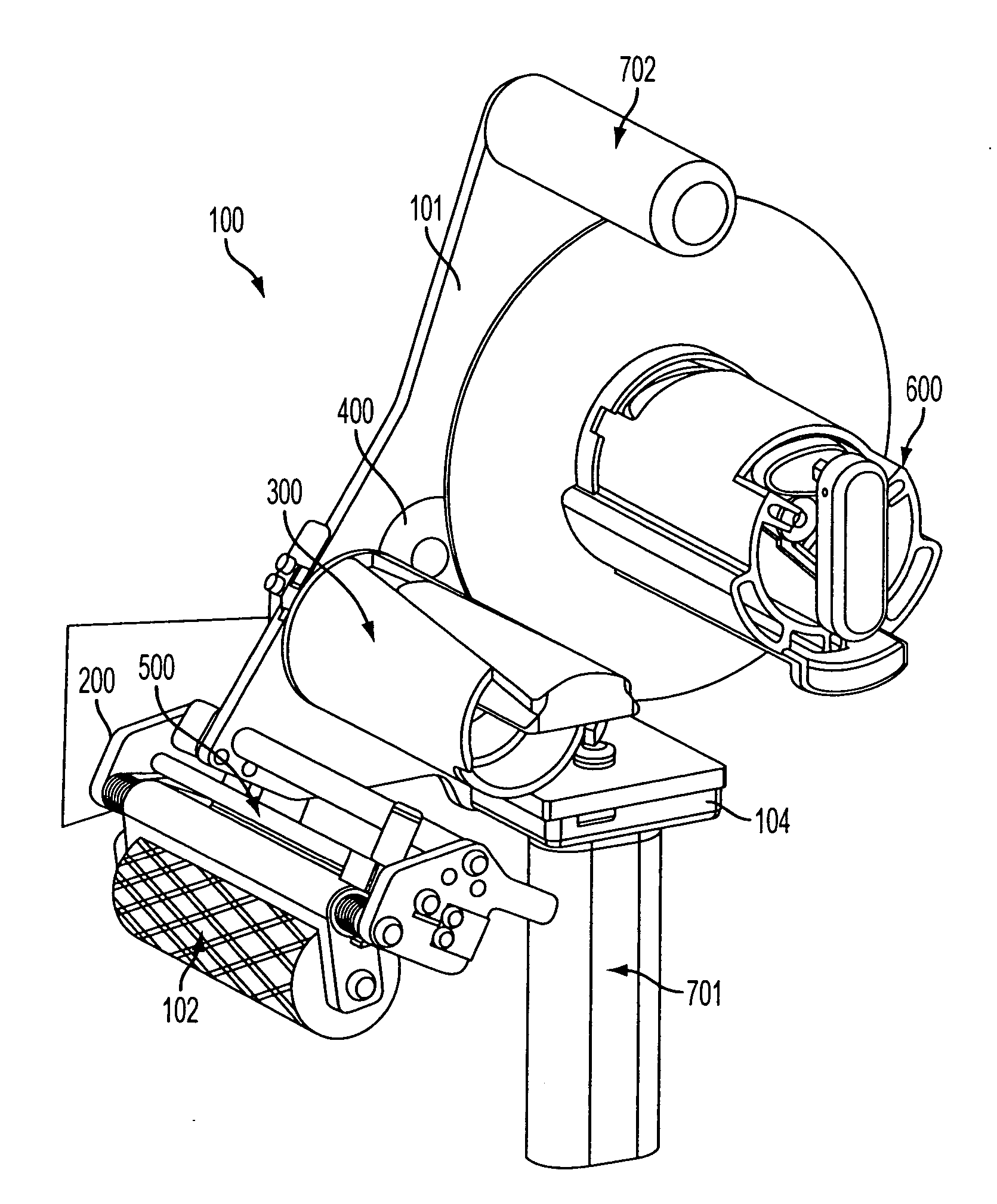
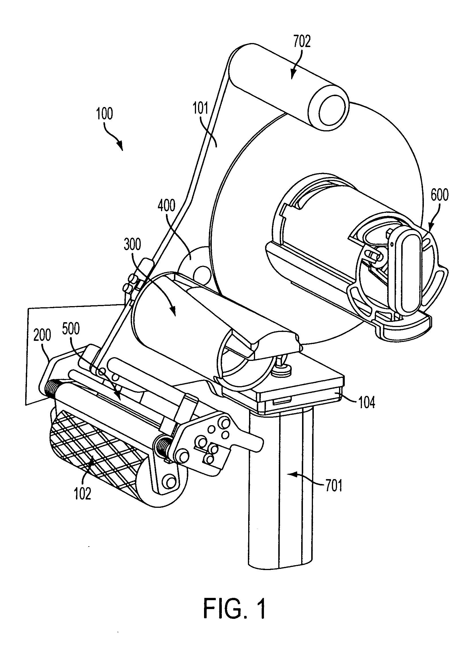
[0012] In a further embodiment, a second hand grip is mountable at a top portion of the frame generally opposite to the first grip. The first grip comprises a first grip body oriented generally perpendicularly to a rotational axis of the tape spool assembly, and the second grip comprises a second grip body oriented generally parallel to the rotational axis of the tape spool assembly. The first grip, which may be a pistol-style handle, is positioned in-line with the applicator roller so that the device user / operator may apply significant force to the applicator roller without generating a radial-ulnar moment about the user's wrist. By this arrangement, the center of gravity of the device with a mounted tape roll is provided over the center of an operator's wrist. It thus takes less effort to apply the adhesive tape throughout the life of the roll, and it makes it easier to apply pressure to the tape as it is being applied to a substrate.
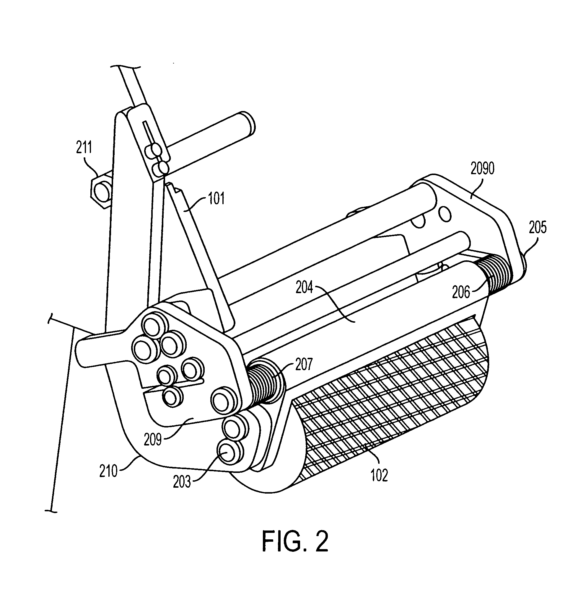
[0026] In addition, by isolating the recessed portions of the pattern with upraised portions on the pressure roller, the network forms barriers to water movement across the pattern. Substrate texture may also be an important consideration. In one embodiment, elements of the upraised roller pattern are angled relative to any directionality presented by the surface texture of the substrate. In one particular embodiment, the upraised portions of the roller pattern have a leading edge inclined at an intersecting angle relative to a texture presented by the substrate surface. This creates an improved seal against water intrusion. The upraised roller pattern also provides good tape seals on relatively smooth, non-textured substrate surfaces.

Problems solved by technology

The use of felt paper has many drawbacks including, but not limited to, the extensive labor needed to apply it and its susceptibility to wind damage before the installation of an outer layer of shingles or other roofing material thereon.
Also, a roof surface often is irregular or uneven.
These prior roofing machines are not designed to be handheld during their operation.
The need to haul a relatively bulky machine on and off roofs is very inconvenient.
Also, bulky roofing machines may not be convenient for use at edges of roofs and / or around upright obstacles commonly encountered on a roof such as chimneys and vent pipes.
In addition, roofs having steeper pitch may not be conducive for operation of a roofing machine thereon needing an operator to maintain a generally upright stance.
Also, the prior roofing machines generally can not also be used for other significant construction site tasks such as wall construction, and so forth.
The process is slow, cumbersome and laborious.
The house wrap is often difficult to install because it is typically in wide, e.g., nine feet wide, rolls, which can be difficult to maneuver by workers on scaffolding or in windy conditions.
The use of the moisture barrier wrap, or a drainage plane increases cost due to increased material and labor cost.
Meeting all of these concerns can be expected to become even more challenging as size and weight of an adhesive tape roll is increased.
Tapes requiring high application pressures are burdensome and tiring, especially in more rigorous work environments such on those involving seam applications for inclined roof construction or wall construction using ladders, since they require a high user-applied application force.
Moreover, the relatively high application pressures commonly applied and required with conventional tape applicator devices do not necessarily result in water-tight seals.

Method used


Image

  • Handheld tape applicator and components thereof, and their methods of use
  • Handheld tape applicator and components thereof, and their methods of use
  • Handheld tape applicator and components thereof, and their methods of use

Examples


example

Example 1

[0121] A tape applicator was used to apply commercial ZIP™ tape over the seams of abutting sheathing panels on a roof. The sheathing panels had an overlay of resin-impregnated Kraft paper and a texture had been embossed into the surface of the overlaid sheathing panel. The texture had a pattern that generally runs in two directions; one along the length of the panel and the second along the width of the panel. The tape applicator was of the type described in FIGS. 1-30 herein and was equipped with a patterned pressure roller (1.5 inch diameter) having diamond shapes cut into its outer peripheral surface generally according to FIG. 2 (average upraised line width of about 0.138 inch; 45 degree angle; 3 diamonds / inch vertical; 2.5 diamonds / inch horizontal; 30 Durometer).

[0122] An excellent water tight seal was provided that was able to pass, with a single pass of the pressure roller over the tape at an application pressure of 4.25 pound force, the ASTM E331-00 “Standard Test...


PUM

PropertyMeasurementUnit
Weightaaaaaaaaaa
Angleaaaaaaaaaa
Angleaaaaaaaaaa

Abstract

A hand-grippable adhesive tape applicator is provided for building construction and other environments. Pressure feedback and integrated slidable cutting mechanism features are included which provide improved tape application performance. Unique tape supply spool and take-up reel assemblies also are provided which enhance tape applicator performance. A patterned applicator roller also is provided to allow tape application to be performed with reduced user-applied force.

Description

FIELD OF THE INVENTION [0001] This invention relates to devices for applying adhesive tape material, and particularly to heavy duty tape applicators for applying adhesive tape to building structures or other surfaces, including components and methods of use thereof. BACKGROUND OF THE INVENTION [0002] The roof and wall structures of residential or commercial buildings are typically constructed by attaching several structural panels to the rafters of an underlying supporting structural frame. The panels are most often placed in a quilt-like pattern with the edge of each panel contacting the edges of adjacent panels so as to form a substantially continuous flat surface atop and surrounding the structural frame. In the case of roofs, a water barrier layer, such as felt paper, is then applied over the panels before the installation of shingles, tiles, shakes, or other outer roofing materials. The use of felt paper has many drawbacks including, but not limited to, the extensive labor need...

Claims


Application Information

Patent Timeline
IPC IPC(8): E04F13/00B32B37/00B44C7/00
CPCB65H35/0033B65H35/0073B65H37/005Y10T156/18B65H2515/34Y10T156/1795B65H2404/521B65H2402/412
Inventor BARKER, JOEL F.CECILIO, FEDERICO R.HATCHETT, DEREK N.KRISTOFEK, GRANT W.MCDERMOTT, PATRICK F.PALM, WILLIAM J. IVROHATGI, GAURAVSCOVILLE, CHRISTOPHER R.STONECIPHER, BRIAN L.WALKER, SHERRY S.WILLIS, DAVID R.PEEK, BRIAN M.
Owner HUBER ENGINEERED WOODS
Learn More