
Nano-composite magnet, quenched alloy for nano-composite magnet, and method for producing them and method for distinguishing them

Inactive Publication Date: 2007-06-14
HITACHI METALS LTD
View PDF13 Cites 11 Cited by
  • Summary
  • Abstract
  • Description
  • Claims
  • Application Information

AI Technical Summary

Benefits of technology

[0047] According to the present invention, nanocomposite magnets, of which the properties are close to those predicted theoretically, can be mass-produced at a good yield.

Problems solved by technology

However, the hard ferrite magnets cannot have that high remanence Br of 0.5 T or more.
However, the Sm—Co based magnet is expensive, because its materials Sm and Co are both expensive.
Nevertheless, it is still expensive to produce the Nd—Fe—B based magnet.
Also, a powder metallurgical process normally requires a relatively large number of process steps by its nature.
However, the only known effective technique of improving the remanence Br is increasing the density of a bonded magnet.
However, none of these proposed techniques are reliable enough to always realize a sufficient “Characteristic value per cost”.
More specifically, none of the nanocomposite magnets produced by these techniques realizes a coercivity that is high enough to actually use if in various applications.

Method used


Image

  • Nano-composite magnet, quenched alloy for nano-composite magnet, and method for producing them and method for distinguishing them
  • Nano-composite magnet, quenched alloy for nano-composite magnet, and method for producing them and method for distinguishing them
  • Nano-composite magnet, quenched alloy for nano-composite magnet, and method for producing them and method for distinguishing them

Examples


example 1

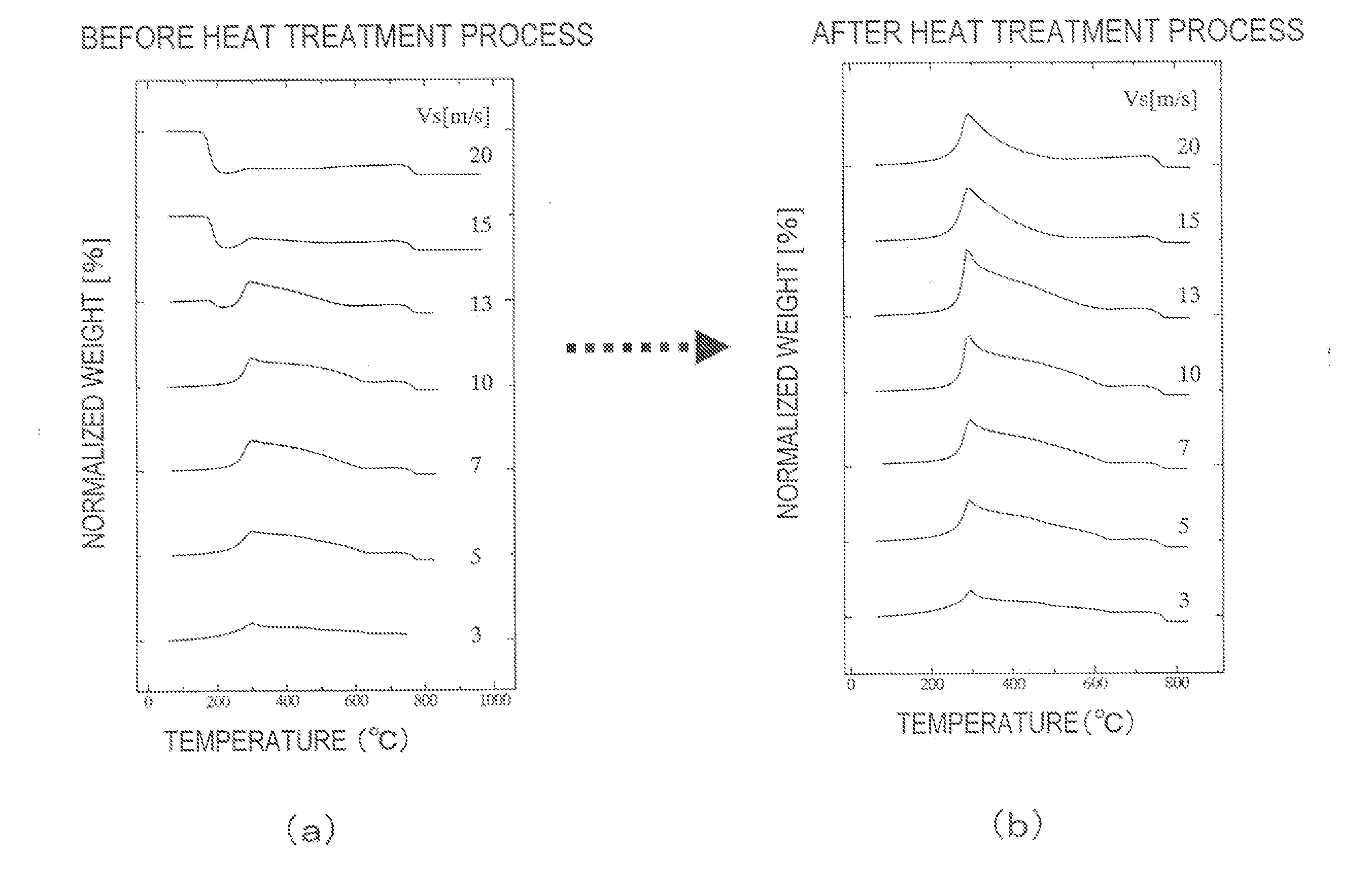
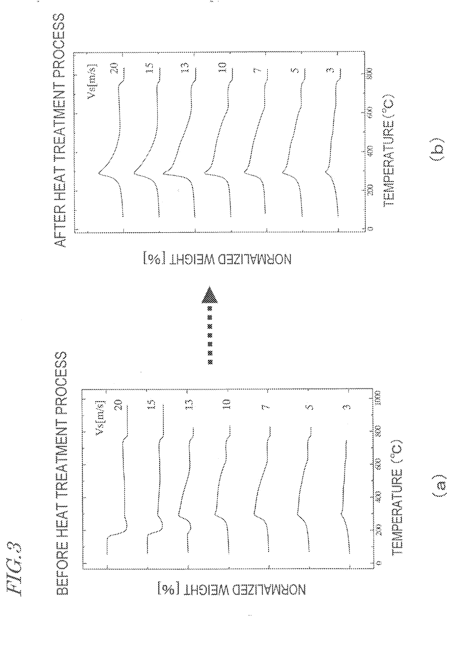
[0108] In a first specific example of the present invention, a molten alloy having a composition Nd7Pr1FebalB12Ti4 was quenched using the melt-quenching machine shown in FIG. 6, thereby making a rapidly solidified alloy in the shape of a ribbon with a thickness of 50 μm to 130 μm. The melt was teemed at a pressure of 30 kPa and at a temperature (melt surface temperature) of 1,400° C. The temperature of the molten alloy was measured on an infrared thermal imagery.

[0109] The rapid cooling conditions were controlled by adjusting the pressure of the argon (Ar) atmosphere within the quenching chamber and the surface velocity Vs of the rotating chill roller. More specifically, the surface velocity Vs of the chill roller was varied within the range of 5 m / s to 20 m / s in the atmosphere having pressures of 1.3 kPa, 33 kPa and 62 kPa.

[0110]FIG. 7 is a graph showing rapid cooling procedures in situations where the roller surface velocities Vs are changed from 5 m / s to 7 m / s, 10 m / s, 13 m / s a...

example 2

[0126] In a second specific example of the present invention, a molten alloy having a composition Nd6.2FebalCo6B11C1Ti5 was quenched, thereby making a rapidly solidified alloy in the shape of a ribbon with a thickness of 50 μm to 130 μm. The rapid cooling conditions and resultant magnet performance are shown in the following Table 1. The conditions not shown in Table 1 are the same as those set for the first specific example described above:

TABLE 1RollersurfaceChamberQuenching rateQuenching ratevelocity Vspressure(1400-900° C.)(900-700° C.)(BH)max[m / s][kPa][105 K / s][105 K / s][kJ / m2]10306.002.42120153015.83.12125173019.13.52120

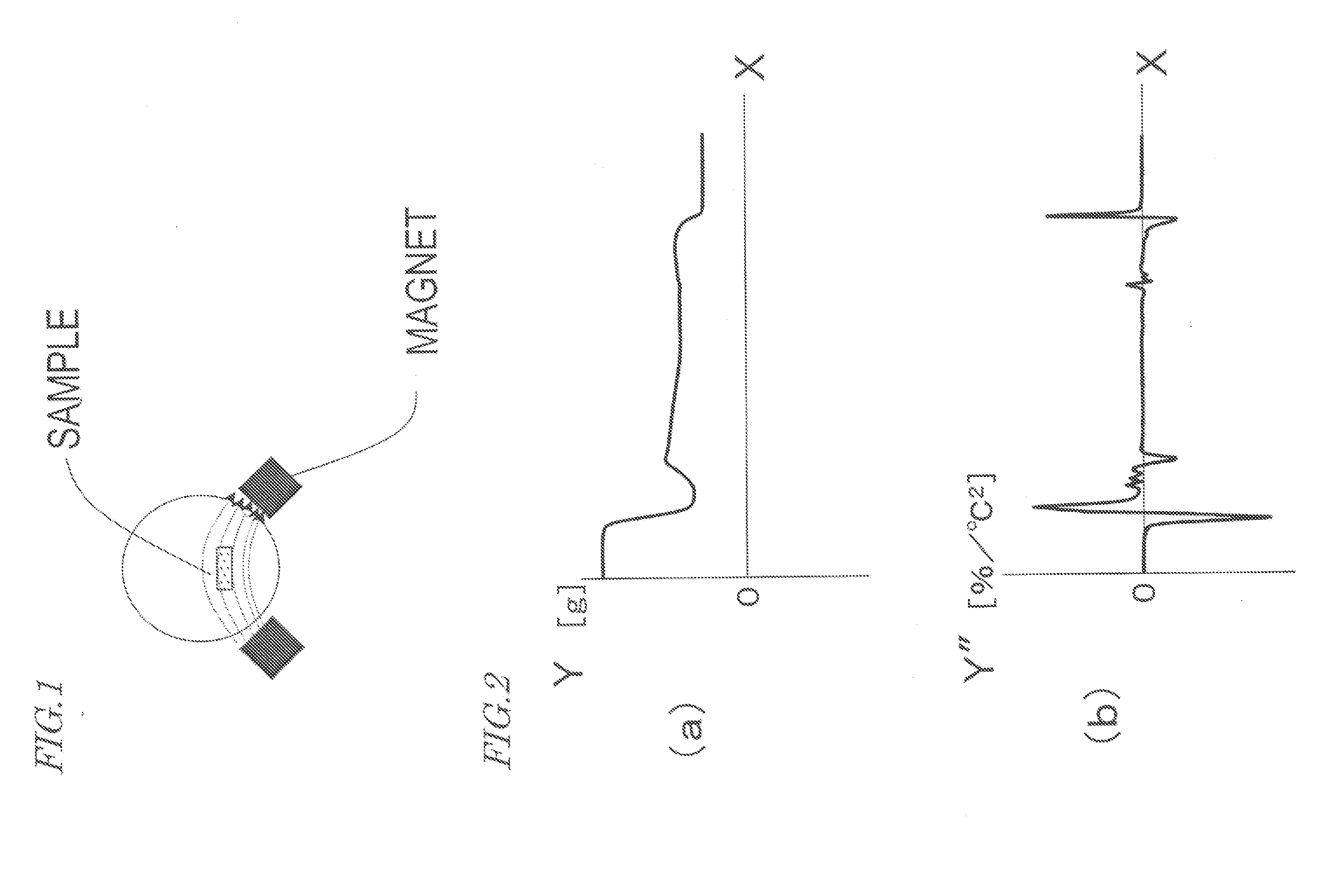
[0127]FIG. 13 is a graph showing the second derivatives of the thermogravimetric curves of this specific example.

[0128] The ω phase produced in the rapidly solidified alloy of this specific example had a Curie temperature of 650° C. to 700° C. This Curie temperature is higher than that of the ω phase of the first specific example due to the difference in allo...


PUM

PropertyMeasurementUnit
Grain sizeaaaaaaaaaa

Abstract

A nanocomposite magnet according to the present invention has a composition represented by the general formula: RxQyMz(Fe1−mTm)bal, where R is at least one rare-earth element, Q is at least one element selected from the group consisting of B and C, M is at least one metal element that is selected from the group consisting of Al, Si, Ti, V, Cr, Mn, Cu, Zn, Ga, Zr, Nb, Mo, Ag, Hf, Ta, W, Pt, Au and Pb and that always includes Ti, and T is at least one element selected from the group consisting of Co and Ni. The mole fractions x, y, z and m satisfy the inequalities of 6 at % ≦x<10 at %, 10 at % ≦y≦17 at %, 0.5 at % ≦z≦6 at % and 0≦m≦0.5, respectively. The nanocomposite magnet includes a hard magnetic phase and a soft magnetic phase that are magnetically coupled together. The hard magnetic phase is made of an R2Fe14B-type compound, and the soft magnetic phase includes an α-Fe phase and a crystalline phase with a Curie temperature of 610° C. to 700° C. (ω phase) as its main phases.

Description

TECHNICAL FIELD [0001] The present invention relates to a nanocomposite magnet including hard magnetic phases and soft magnetic phases that have very small sizes and that are magnetically coupled together. BACKGROUND ART [0002] Recently, it has become more and more necessary to further enhance the performances of, and further reduce the size and weight of, consumer electronic appliances, office automation appliances and various other types of electric equipment. For these purposes, a permanent magnet for use in each of these appliances is required to maximize its performance to weight ratio when operated as a magnetic circuit. For example, a permanent magnet with a remanence BR of 0.5 T (tesla) or more is now in high demand. Hard ferrite magnets have been used widely because magnets of this type are relatively inexpensive. However, the hard ferrite magnets cannot have that high remanence Br of 0.5 T or more. [0003] An Sm-Co based magnet, produced by a powder metallurgical process, i...

Claims


Application Information

Patent Timeline
IPC IPC(8): H01F1/057B22D11/06H01F1/058H01F41/02
CPCB22D11/0611B82Y25/00H01F1/0579H01F1/058H01F41/0253
Inventor SHIGEMOTO, YASUTAKAHIROSAWA, SATOSHIMIYOSHI, TOSHIO
Owner HITACHI METALS LTD
Learn More