Check patentability & draft patents in minutes with Patsnap Eureka AI!

Auxiliary power unit for a diesel powered transport vehicle

a technology for auxiliary power units and transport vehicles, applied in the direction of machines/engines, mechanical energy handling, mechanical equipment, etc., can solve the problems of affecting the efficiency of the operation of the engine affecting the efficiency of the operation of the transport vehicle, and affecting the efficiency of the operation. , to achieve the effect of high efficiency

Inactive Publication Date: 2007-06-14
ENERGY & ENGINE TECH
View PDF5 Cites 44 Cited by
  • Summary
  • Abstract
  • Description
  • Claims
  • Application Information

AI Technical Summary

Benefits of technology

[0007] Accordingly, there is disclosed a high efficiency auxiliary power unit (APU) for a transport vehicle powered by an internal combustion engine. The APU comprises an air-cooled engine that uses the fuel supply and the engine exhaust system of the transport vehicle and has an integral, forced-air cooling system. An air-cooled, brushless generator, having an integral, forced-air cooling system and directly coupled to an output shaft of the air-cooled engine, provides simultaneous high voltage AC and low voltage DC outputs. An enclosure surrounds the air-cooled engine and the air-cooled brushless generator and provides protection and mechanical support. A system of first and second air ducts within the enclosure separately conveys cooling air into and through the air-cooled engine and the brushless generator respectively. The cooling air, drawn into the first and second air ducts by respective direct drive fan devices integrated in the air-cooled engine and in the brushless generator, exits from the enclosure through first and second air outlets.

Problems solved by technology

Idling these large engines bums significant amounts of fuel, far in excess of the amount needed to provide power for these benefits to the drivers.
Such diesel fuel consumption needlessly consumes a non-renewable energy resource, burdens the costs of shipping goods with unnecessary expense, and results in significant amounts of air and noise pollution.
Idling the engines of these transport vehicles for substantial periods of time also violate various federal, state and local laws and regulations.
In addition to the costs of the wasted fuel and the environmental impacts of overnight idling are the higher maintenance costs due the excess wear that results from running the engines for uses other than pulling a loaded trailer and increased health costs to treat illnesses caused by the emissions from the engines.
However, each of these conventional systems has one or more of the following disadvantages: (1) the engine of the APU is water cooled and must be tied into the radiator system of the truck or be provided with its own radiator, hoses, water pump, etc.
; (2) the engine of the APU drives the alternator or generator via a belt drive, which is associated with reduced efficiency, reliability, and additional maintenance costs; (3) the APU mechanically drives the A / C compressor for an auxiliary cooling system located in the cabin of the truck; (4) the APU requires extensive integration into the truck fuel, cooling, exhaust and electrical systems, which increases the cost of installing and maintaining the APU and reduces the reliability of the combined systems; (5) the integration of the APU into the truck systems increases the mechanical complexity thereof resulting in reduced reliability; and (6) the APU itself tends to be heavier and less efficient than it could be using modem technology.
Conventional auxiliary power units also use some form of adapter that employs a belt, chain, clutch or gear set to couple the engine to the generator, which adds weight, mechanical complexity and additional maintenance requirements.
The additional circuitry adds weight, complexity, maintenance requirements and cost, all without improving the conversion efficiency of the auxiliary power unit.

Method used


Image

  • Auxiliary power unit for a diesel powered transport vehicle
  • Auxiliary power unit for a diesel powered transport vehicle
  • Auxiliary power unit for a diesel powered transport vehicle

Examples


Embodiment Construction

[0021] In the following description the term transport vehicle is taken generally to mean a motorized vehicle, such as a truck, ship or airplane, usually driven by a driver or pilot and used for the shipment of goods over long distances. In the disclosed embodiment a transport vehicle is along-haul, diesel powered truck. This type of vehicle often includes a sleeping compartment in the cabin (cab) of the truck tractor unit. This cab is typically equipped with a heating and air conditioning unit, lighting, electrical outlets and small appliances, all of which are powered by an electric generator driven by the truck's engine or an auxiliary engine. Nevertheless, a transport vehicle could as easily be a boat equipped for the same type of shipping service, or even an aircraft configured for long distance hauling to remote areas, for example.

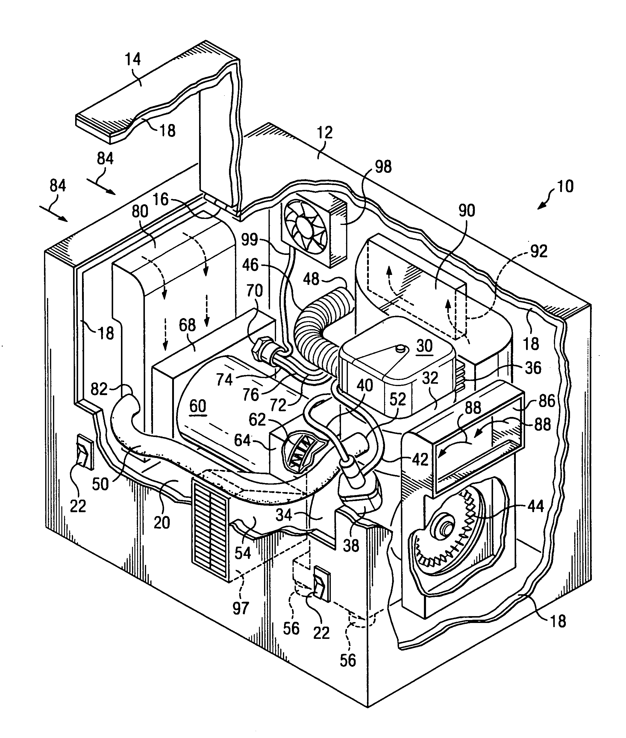
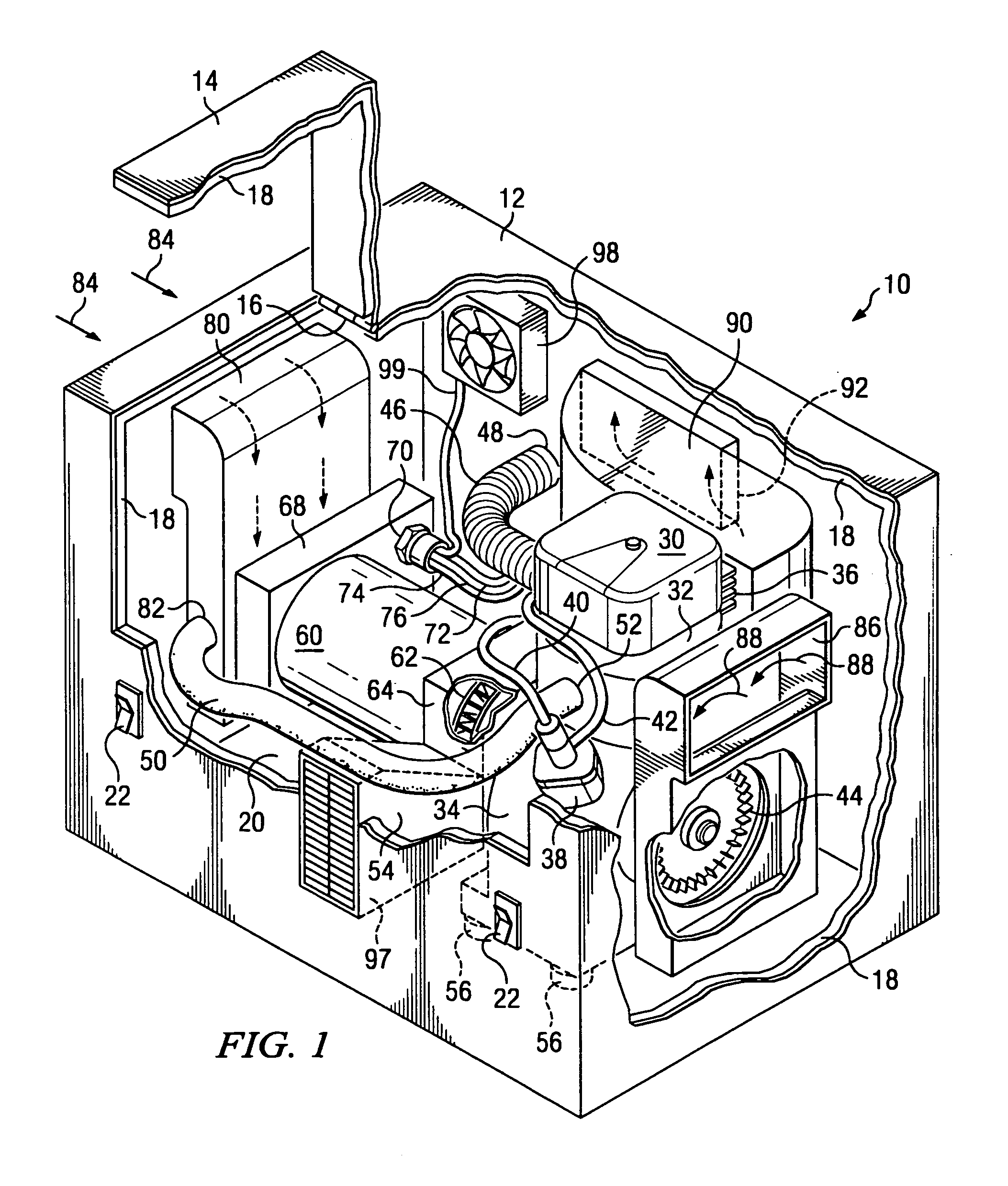
[0022] Referring to FIG. 1, there is illustrated an isometric view, partially cutaway, of the front, left corner of one embodiment of an auxiliary ...


PUM


Abstract

There is disclosed a system for use in transport vehicles, comprising in combination an auxiliary power unit (APU) for a transport vehicle powered by a diesel engine and having a fuel system, an engine exhaust system and a battery powered electrical system; an engine exhaust adapter wherein engine exhaust from the air-cooled diesel engine is directly coupled through the exhaust adapter installed in-line with an exhaust pipe of the transport vehicle between the engine of the transport vehicle and the muffler of the transport vehicle; and a locator unit for use in a tracking and monitoring system for communicating over a communication network with the locator unit and with a remote location for the APU, wherein the locator unit is attached to or installed within the APU.

Description

PRIORITY AND RELATED APPLICATIONS [0001] This application is a continuation of and claims priority under 35 U.S.C. § 120 to application Ser. No. 10 / 794,447 filed Mar. 5, 2004, entitled “Auxiliary Power Unit for A Diesel Powered Transport Vehicle,” the entire contents of which are incorporated by reference.Field of the Invention [0002] The invention generally relates to auxiliary power units and, more particularly, to auxiliary power units for use on transport vehicles powered by internal combustion engines to provide electrical power during periods when the transport vehicle's main engine must be shut off, and to auxiliary power units used in combination with a locator unit for use in a tracking and monitoring system. Background [0003] Approximately one-half million diesel-powered trucks provide long-haul transport of goods throughout the United States. A common practice among truckers is to leave the diesel engines that power these trucks running—i.e., idling—during overnight stops...

Claims


Application Information

Patent Timeline
IPC IPC(8): H02K7/18F02B63/04
CPCF01N13/08F01N13/1805F02B63/04F02B63/044F01N2590/08
Inventor WURTELE, ROGER N.MCANDREW, WILLARD G.
Owner ENERGY & ENGINE TECH
Features
  • R&D
  • Intellectual Property
  • Life Sciences
  • Materials
  • Tech Scout
  • Unparalleled Data Quality
  • Higher Quality Content
  • 60% Fewer Hallucinations
Learn More