

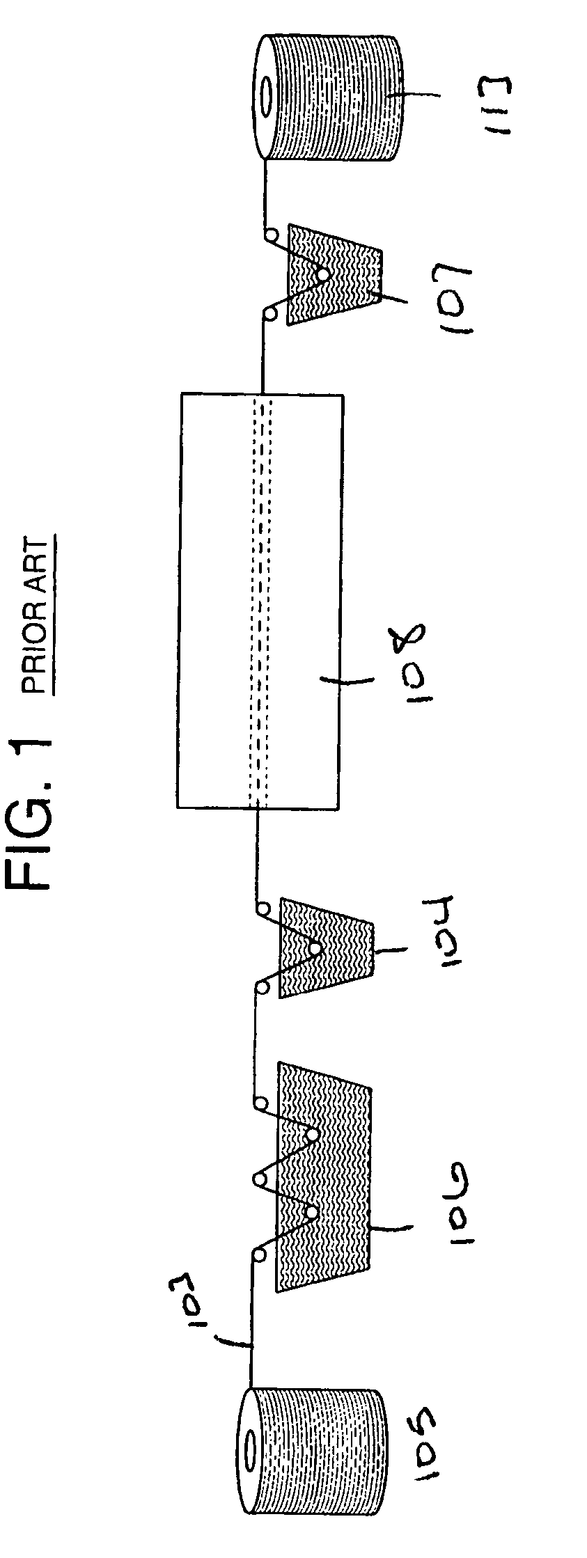
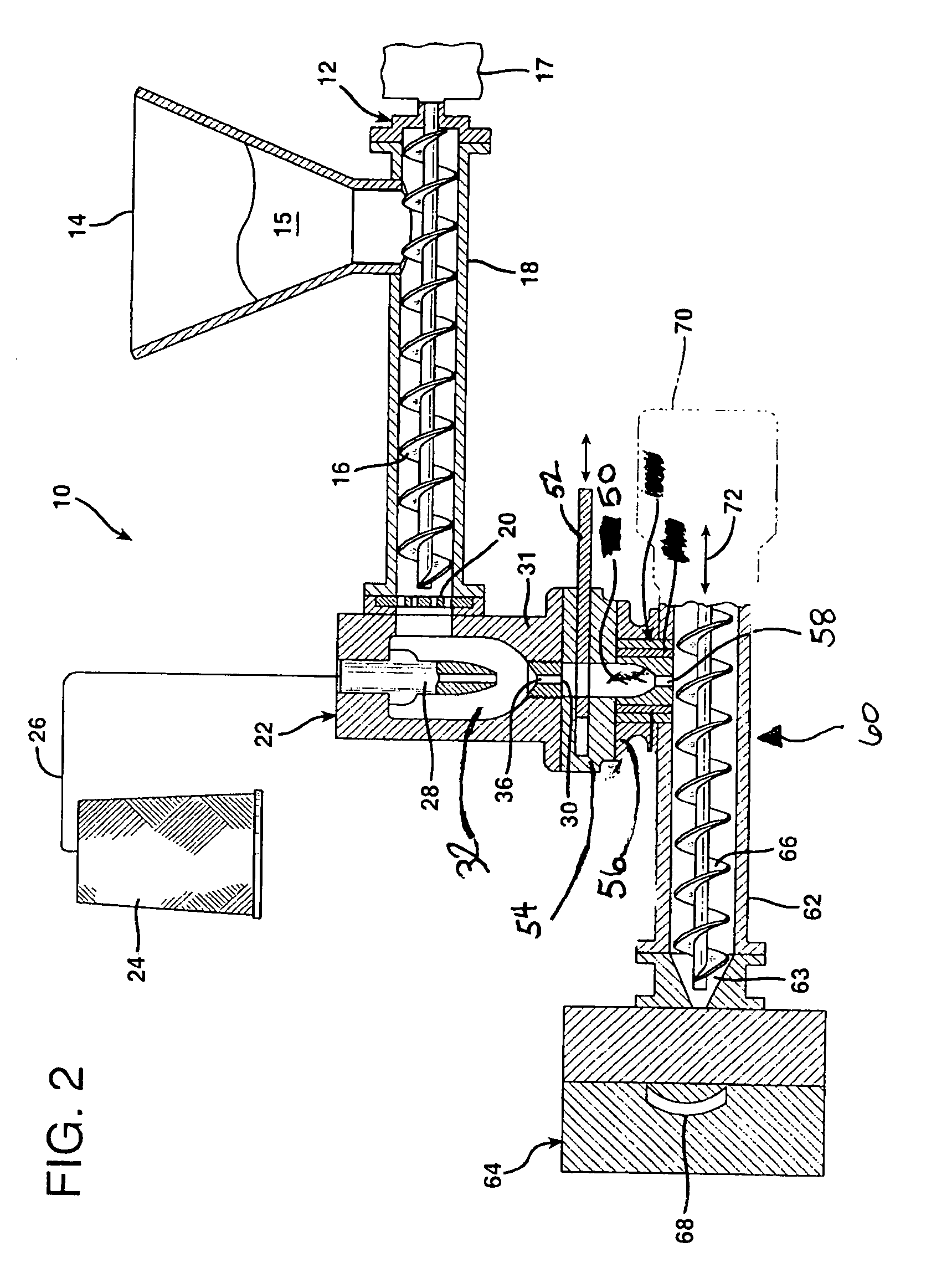
Long fiber thermoplastic process for conductive composites and composites formed thereby
a thermoplastic process and composite material technology, applied in the field of polymer articles, can solve the problems of reducing the mechanical strength of the final product, poor powder dispersion, and shortened fibers imparting reduced electromagnetic shielding properties to the composite material, etc., to achieve enhanced surface aesthetics, reduce the loading of fibers, and improve the effect of impact resistan
- Summary
- Abstract
- Description
- Claims
- Application Information
AI Technical Summary
Benefits of technology
Problems solved by technology
Method used
Image

Examples
examples
[0033] The following examples are prophetic and all mechanical and shielding properties are estimated. In Example 1, acrylonitrile-butadiene-styrene (ABS) polymer is melted and 10% by weight Nickel coated carbon (NCC) fibers are added to the ABS. The fibers are cut to length and the ABS / fiber melt is extruded to form a composite part.
[0034] In Example 2, ABS polymer is melted and 7.5% by weight NCC fibers are added to the ABS. The fibers are cut to length and the ABS / fiber melt is extruded to form a composite part.
[0035] In Example 3, ABS polymer is melted and 5.0% by weight NCC fibers are added to the ABS. The fibers are cut to length and the ABS / fiber melt is extruded to form a composite part. The properties of the examples are estimated below.
PUM
| Property | Measurement | Unit |
|---|---|---|
| electromagnetic shielding efficiency | aaaaa | aaaaa |
| electromagnetic shielding efficiency | aaaaa | aaaaa |
| frequency | aaaaa | aaaaa |
Abstract
Description
Claims
Application Information