Coated carbon nanotube array electrodes

a carbon nanotube and array electrode technology, applied in secondary cells, electrochemical generators, cell components, etc., can solve problems such as defects that produce electrically-insulating domains on the substrate surface, and achieve the effect of enhancing electrical conductivity

Inactive Publication Date: 2007-06-14
TRUSTEES OF BOSTON COLLEGE THE
View PDF18 Cites 36 Cited by
  • Summary
  • Abstract
  • Description
  • Claims
  • Application Information

AI Technical Summary

Benefits of technology

[0012] In one aspect, the present invention provides a uniform film coating comprising an electrically conducting polymer, such as for example, polypyrrole (PPy) on a CNT substrate material having linear, longitudinally aligned array of tubules. The electro-deposition of conductive polymeric films on the CNT substrate material is preferably carried out in an inert atmosphere (in the absence of oxygen) to provide a surface coatings that are distributed uniformly and contiguously over the entire tubule surface. In another aspect, the CNT substrate material is pretreated with an aqueous acid, such as a mineral acid, to improve conductive polymer film adhesion to the substrate surface.
[0014] An advantage of the CNT coating methods of the present invention is that they enable the formation of highly uniform, contiguous, thin electrically conducting polymer films on a light weight mechanically strong, highly porous CNT substrate. The methods of the invention, therefore, provide electrode materials for fabrication of electrodes that are capable of superior electrical charge retention properties, enabling their use in high performance energy storage devices such as rechargeable batteries relative to conventional materials. Such devices utilizing electrodes of the present invention therefore, provide advantages of portability and fewer charge cycle requirement in comparison with devices containing conventional electrodes. The CNT electrode materials of the present invention, therefore, improve both performance and life of rechargeable batteries.
[0018] It is yet another aspect of the present invention to provide CNT electrodes containing electrically conducting polymers that are doped with n-type or p-type dopants for enhanced electrical conductivity.

Problems solved by technology

Such limitations include film non-uniformity and variable coating thickness, which result in producing defects that produce electrically-insulating domains on the substrate surface.

Method used


Image

  • Coated carbon nanotube array electrodes
  • Coated carbon nanotube array electrodes
  • Coated carbon nanotube array electrodes

Examples


example 1

Synthesis of Well-aligned Carbon Nanotubes (CNTS)

[0057] Well-aligned carbon nanotubes were obtained by methods disclosed in the art (see Z. F. Ren, et al., Science 282 (1998) 1105; Z. P. Huang et al. Appl. Phys. Lett. 73 (1998) 26; Z. F. Ren, et al., Proceedings of the 13th International Winter School on Electronic Properties of Novel Materials, (1999) 263; Z. F. Ren, et al., Appl. Phys. Lett., 75 (1999) 1086; and Z. F. Ren, et al., Proceedings of the 32nd International Technical Conference of the Society for the Advancement of Materials and Process Engineering (SAMPE), Nov. 5-9, 2000, Boston, USA, pp. 200-204). Titanium (Ti) is used as base substrate upon which a thin nickel (Ni) layer of about 15-25 nm was surface coated by magnetron sputtering to function as a catalyst for CNT growth. The CNTs obtained by this method have tubule diameters ranging from 50-100 nm and tubule lengths of 8-10 μm. Tubule diameter and length is controlled by varying the Ni layer thickness and growth t...

example 2

PPy Deposition and Electrochemical Measurements

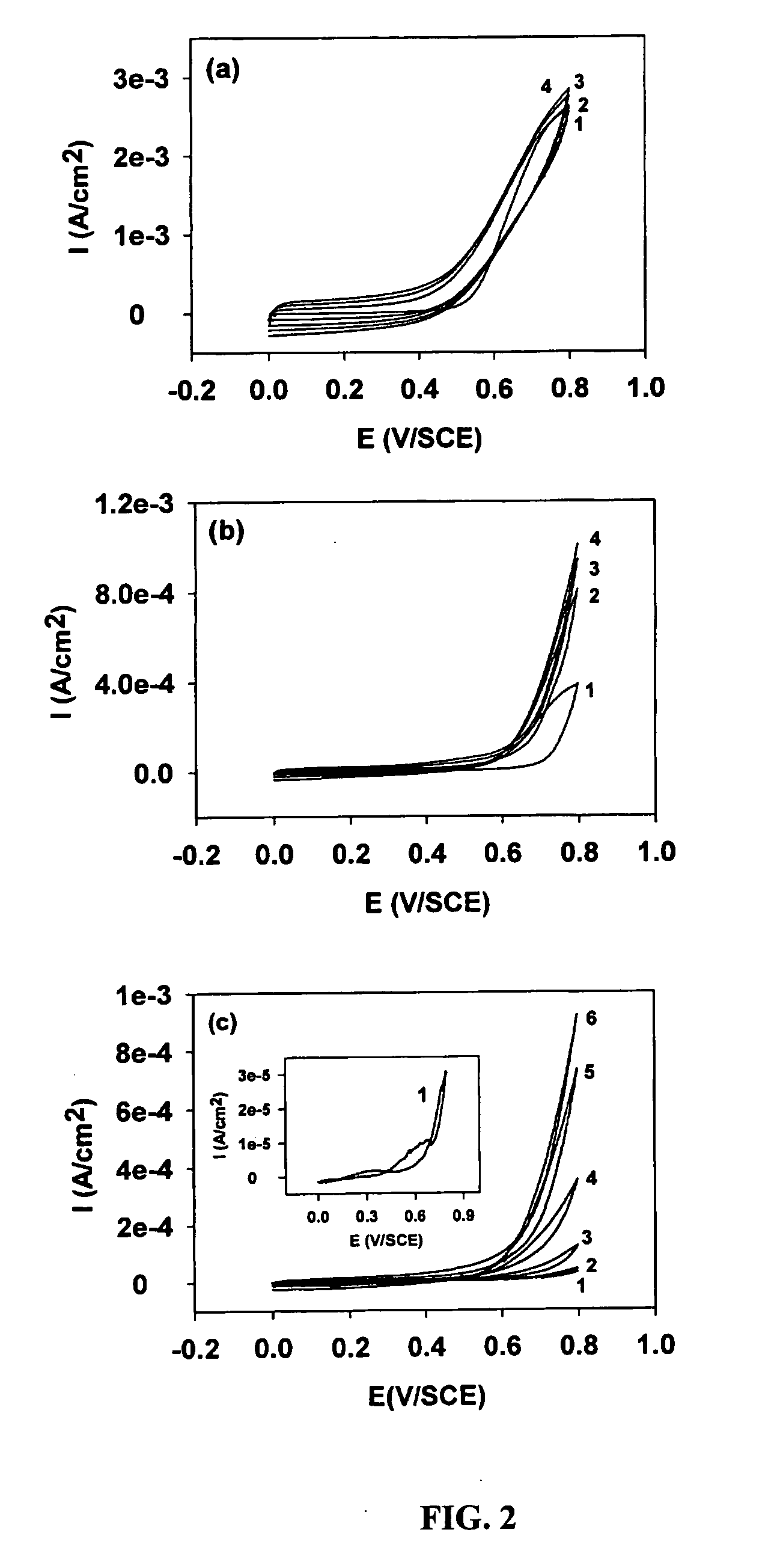
[0058] PPy films were deposited on CNT substrates by in-situ polymerization of pyrrole potentiodynamically using a standard three-electrode cell from 17.3 mM pyrrole (Aldrich) and 0.1M LiClO4 (Aldrich, A.C.S reagent) aqueous solutions. A PC4 potentiostat / Galvanostat (Gamary Instruments Inc., Warminster, Pa. 18974) was employed for the synthesis and cyclic voltammetric (CV) measurements of PPy films. Platinum wire was used as the counter electrode, and a saturated calomel electrode (SCE) was used as the reference electrode. Prior to PPy deposition, the CNT substrates were pretreated in 15% wt. HNO3 aqueous solution for 30 minutes to remove non-adherent metallic Ni catalyst particles and also to increase electrochemical activity of the surface of the CNTs in water and aqueous solutions. After PPy deposition, the substrates were soaked in double distilled water for 30 minutes to remove unreacted pyrrole monomer. Redox processes of the PP...

example 3

Characteristics of PPy Films Polymerized on CNT Substrates

Film Thickness

[0059] PPy coatings obtained on CNT substrates via the in-situ polymerization methods provides highly uniform films on the surface of individual CNT tubules. A typical film thickness of about 90 nm is obtained by passing a charge of about 1308.6 mC / cm2 on the outer surface of individual tubules. In comparison, film thickness of about 1.1 μm and about 1.5 μm, are obtained upon passing a charge of about 645 mC / cm2 and about 933 mC / cm2 on Ti and Pt surfaces respectively.

Film Morphology

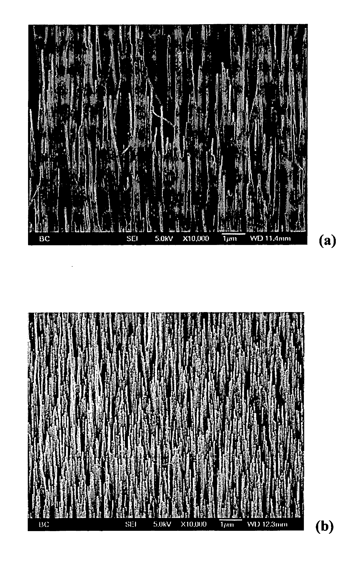
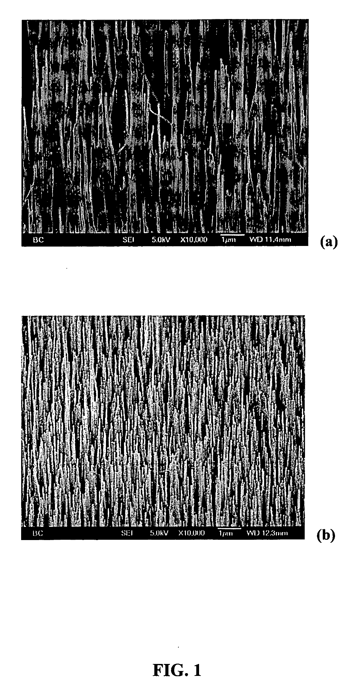
[0060] PPy film morphologies are dependant on film thickness film formation charge (Qfilm). A small film formation charge (Qfilm) results in a thin PPy coating (about 8 to 10 nm), coated CNT substrates that are not free-standing. The CNT tubules form bundles as a result of surface tension. With increase in Qfilm, the thickness of the PPy films on the tubule surface increases to about 90 nm, providing mechanically strong, coated...


PUM

PropertyMeasurementUnit
thicknessaaaaaaaaaa
lengthaaaaaaaaaa
diameteraaaaaaaaaa

Abstract

The present invention provides conductive carbon nanotube (CNT) electrode materials comprising aligned CNT substrates coated with an electrically conducting polymer, and the fabrication of electrodes for use in high performance electrical energy storage devices. In particular, the present invention provides conductive CNTs electrode material whose electrical properties render them especially suitable for use in high efficiency rechargeable batteries. The present invention also provides methods for obtaining surface modified conductive CNT electrode materials comprising an array of individual linear, aligned CNTs having a uniform surface coating of an electrically conductive polymer such as polypyrrole, and their use in electrical energy storage devices.

Description

RELATED APPLICATIONS [0001] This application is a divisional of U.S. application Ser. No. 10 / 305,804, filed Nov. 27, 2002, which claims priority to U.S. Provisional Application Ser. No. 60 / 334,328, filed on Nov. 30, 2001, and the entirety of these applications are hereby incorporated herein by reference for the teachings therein.STATEMENT AS TO FEDERALLY SPONSORED RESEARCH [0002] The present invention was made with partial support from the US Army Natick Soldier Systems Center under grant No. DAAD 16-00-C-9227, Department of Energy under grant No. [0003] DE-FG02-00ER45805, the National Science Foundation under grant No. DMR-9996289 and the US Army Research Office under grant No. DAAD19-00-1-0001.FIELD OF THE INVENTION [0004] The present invention relates generally to electrically conductive carbon nanotube electrode materials, methods for their preparation and their use as electrodes in high performance rechargeable batteries. BACKGROUND OF THE INVENTION [0005] Carbon nanotubes (CNT...

Claims


Application Information

Patent Timeline
Patent Type & Authority Applications(United States)
IPC IPC(8): H01M4/66H01M4/60H01M4/04C25D5/56C25D11/00H01G9/00H01G9/155H01L51/00H01L51/30H01M4/133H01M4/137H01M4/36H01M4/58H01M4/583H01M4/90H01M4/96
CPCB82Y10/00Y10S977/857H01G9/155H01L51/0048H01L51/0052H01M4/133H01M4/137H01M4/366H01M4/583H01M4/602H01M4/663H01M4/96Y02E60/122Y02E60/13Y02E60/50Y10S977/742Y10S977/948B82Y30/00Y02E60/10H01G11/36H01G11/38H01G11/48H01G11/24H10K85/221H10K85/615
Inventor REN, ZHIFENGWEN, JIANCHEN, JINGHUAHUANG, ZHONGPINGWANG, DEZHI
Owner TRUSTEES OF BOSTON COLLEGE THE
Why Eureka
Try Eureka