
Metering technique for lateral flow assay devices

a technology of lateral flow and assay device, which is applied in the direction of measurement device, biological material analysis, instruments, etc., can solve the problems of undue pain to patients, uncontrollable flow, and association of construction types, so as to facilitate the flow of test sample and prevent migration of test sampl

Active Publication Date: 2007-06-14
KIMBERLY-CLARK WORLDWIDE INC
View PDF99 Cites 49 Cited by
  • Summary
  • Abstract
  • Description
  • Claims
  • Application Information

AI Technical Summary

Benefits of technology

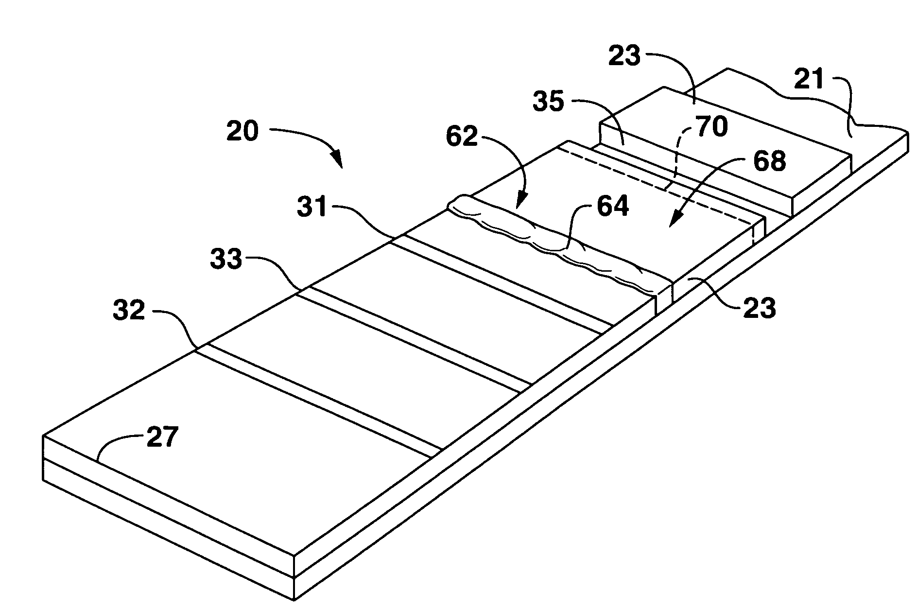
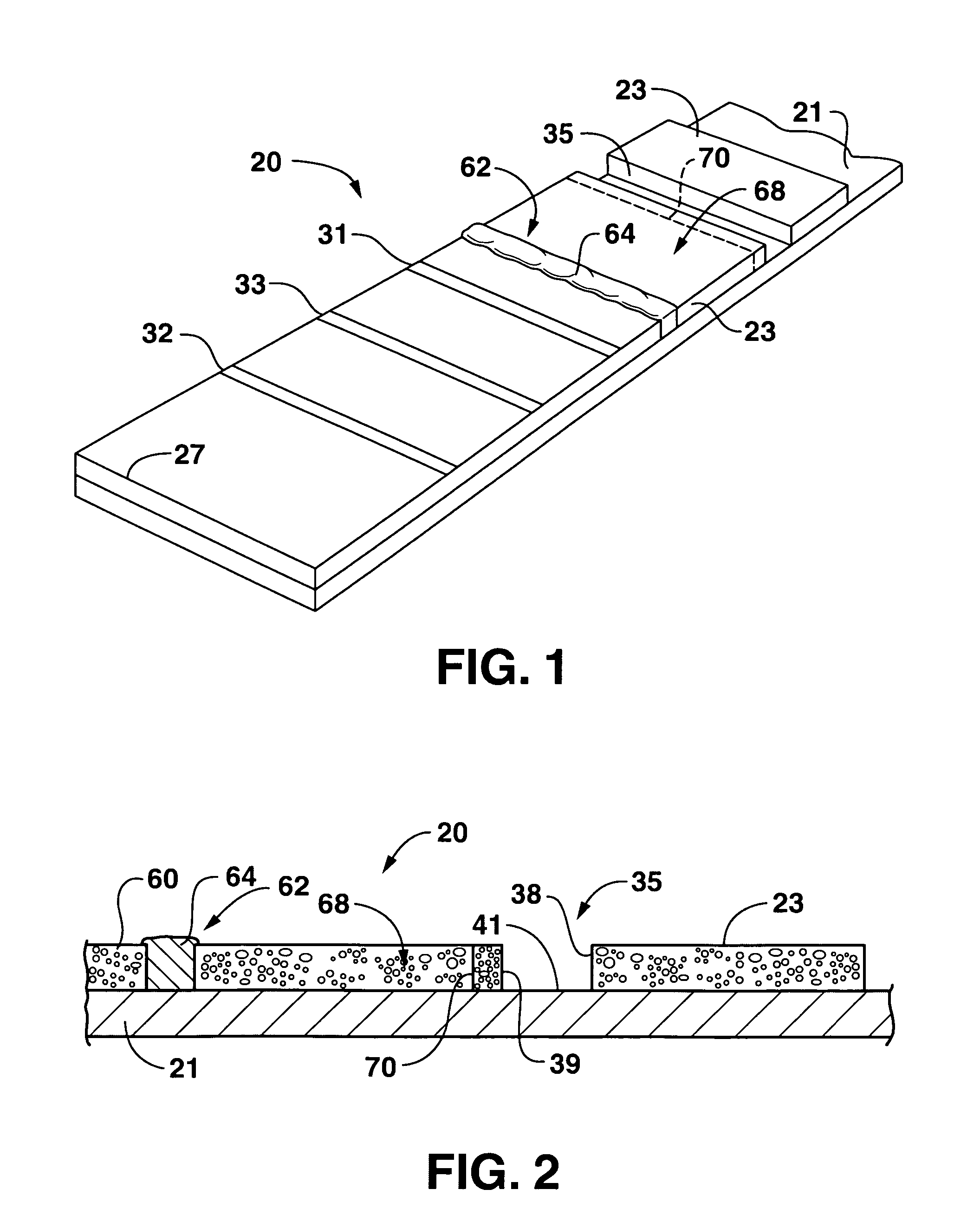
[0005] In one embodiment, the barrier may be defined by a soluble composition in a defined band across the width of the membrane, with the soluble composition present throughout the membrane in an amount to prevent migration of the test sample from the collection region to the detection region. The soluble composition may be dissolved by the diluent and is selected so as to not to affect detection of the analyte in the test sample.
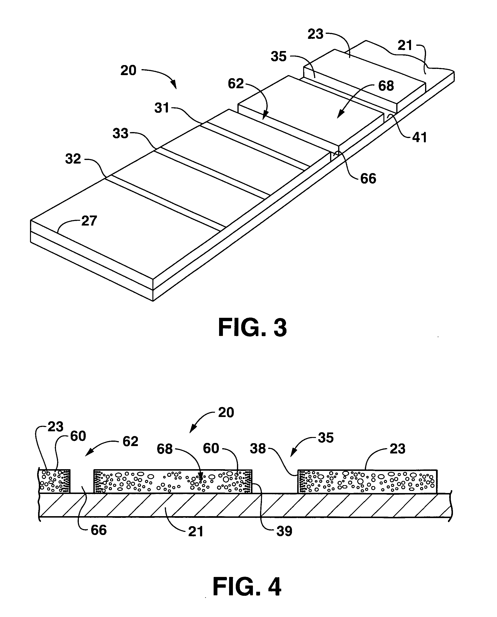
[0011] Any channel structure defined in the membrane may be formed by a suitable microfabrication technique that renders at least a portion of the channel essentially non-conductive to the test sample. Such a technique may include laser ablation or applying a solvent treatment to the membrane. In this instance, a bridging member may be used to conduct the test sample from the channel to the collection region. The channel may be treated with a hydrophobic agent to promote rapid collection of the test sample within the channel.

Problems solved by technology

However, this type of construction is associated with a number of problems.
For example, when the test strip is inserted into an instrument for measurement, the potentially infectious sample material may contact parts of the optical reader and result in contamination.
However, when the test sample is blood, the collection of a large sample may cause undue pain to the patient.
Unfortunately, variations associated with sample transfer and diffusion of the sample to the membrane result in a flow that is largely uncontrolled and uneven before reaching the detection zone.
This may have an adverse affect on the accuracy of the device because the amount of analyte and / or label captured across the detection zone is not consistent at the time of measurement.

Method used


Image

  • Metering technique for lateral flow assay devices
  • Metering technique for lateral flow assay devices
  • Metering technique for lateral flow assay devices

Examples


Embodiment Construction

Definitions

[0022] As used herein, the term “analyte” generally refers to a substance to be detected. For instance, analytes may include antigenic substances, haptens, antibodies, and combinations thereof. Analytes include, but are not limited to, toxins, organic compounds, proteins, peptides, microorganisms, amino acids, nucleic acids, hormones, steroids, vitamins, drugs (including those administered for therapeutic purposes as well as those administered for illicit purposes), drug intermediaries or byproducts, bacteria, virus particles and metabolites of or antibodies to any of the above substances. Specific examples of some analytes include ferritin; creatinine kinase MB (CK-MB); digoxin; phenytoin; phenobarbitol; carbamazepine; vancomycin; gentamycin; theophylline; valproic acid; quinidine; luteinizing hormone (LH); follicle stimulating hormone (FSH); estradiol, progesterone; C-reactive protein; lipocalins; IgE antibodies; cytokines; vitamin B2 micro-globulin; glycated hemoglobi...


PUM


Abstract

A diagnostic method and associated test kit for detecting an analyte residing in a test sample is provided. A sample membrane is utilized having a collection region and a detection region, the collection region having a known saturation volume for the intended test sample. A barrier is defined between the collection region and the detection region. The collection region is saturated with the test sample having a volume of less than about 100 microliters so that a known volume of the test sample is contained in the collection region. The barrier is removed from between the collection region and detection region of the membrane and a diluent is supplied to the collection region of the membrane to facilitate flow of the test sample from the collection region to the detection region of the membrane.

Description

BACKGROUND OF THE INVENTION [0001] Test strips are often used for qualitative and quantitative analysis of blood components. The test strips are sometimes constructed so that the sample application area and the detection area are stacked above one another in a vertical axis. However, this type of construction is associated with a number of problems. For example, when the test strip is inserted into an instrument for measurement, the potentially infectious sample material may contact parts of the optical reader and result in contamination. Thus, spatial separation between the sample application area and detection zone is often desired, i.e., lateral flow strips. Most conventional lateral flow strips are designed for test samples that are readily available in large quantities (e.g., urine). However, when the test sample is blood, the collection of a large sample may cause undue pain to the patient. Thus, one technique that has been utilized to accommodate smaller test sample volumes i...

Claims


Application Information

Patent Timeline
IPC IPC(8): G01N33/558
CPCG01N33/558Y10S436/825Y10T436/25625Y10T436/108331Y10T436/107497Y10T436/25375G01N33/54388
Inventor TAKEUCHI, JAMES M.SONG, XUEDONGYANG, KAIYUANWEI, NINGFEASTER, SHAWN R.
Owner KIMBERLY-CLARK WORLDWIDE INC
Learn More