Device comprising at least one type of tubular nanostructure having at least one complex pigment on the surface thereof

a tubular nanostructure and complex technology, applied in the field of tubular nanostructures having at least one complex pigment on the surface thereof, can solve the problems of reducing the performance characteristics of nanotubes, dispersing such amounts of nanotubes, and limiting the use of carbon nanotubes as fillers, so as to improve energy conversion efficiency and life, improve performance characteristics, and broaden the field of applications of such devices.

Inactive Publication Date: 2007-06-21
NANOLEDGE
View PDF0 Cites 45 Cited by
  • Summary
  • Abstract
  • Description
  • Claims
  • Application Information

AI Technical Summary

Benefits of technology

[0027] The object of the present invention is to improve the performance characteristics, in terms of energy conversion efficacy and life, of photovoltaic devices based on conjugated polymers.
[0028] The present invention will also make it possible to broaden the field of

Problems solved by technology

However, these suspensions are only suspensions either in pure water or in aqueous solutions.
However, on the one hand the carbon nanotubes are Single-wall nanotubes which have been modified by the attachment of an amine or an alkylarylamine to their surface, and on the other hand the intrinsic properties of the nanotubes are degraded due to their chemical modification on the surface and the destruction of carbon-carbon bonds by the grafting of amine groups onto the structure.
The fact that it is currently impossible to disperse such amounts of nanotubes in organic solvents that are insoluble in or immiscible with water, and hence to integrate these nanotubes homogeneously into an organic matrix that is immiscible with or insoluble in water, constitutes an obstacle to the use of carbon nanotubes as a filler.
Production of the semiconductor materials used in these devices requires high manufacturing temperatures, and the photovoltaic cells only achieve optimum performance

Method used


Image

  • Device comprising at least one type of tubular nanostructure having at least one complex pigment on the surface thereof
  • Device comprising at least one type of tubular nanostructure having at least one complex pigment on the surface thereof
  • Device comprising at least one type of tubular nanostructure having at least one complex pigment on the surface thereof

Examples


example 1

denoted by XF003 in Table 1

[0180] 9.5 mg of bare carbon nanotubes, 12.3 mg of pigment and 4.0 mg of polymer, i.e. a weight ratio nanotubes / pigment / polymer of 1 / 0.3 / 0.42, were mixed by dry grinding in a ball mill.

[0181] 5000.13 mg of xylene are added to this mixture and the whole is mixed by bath sonication for 2×15 minutes.

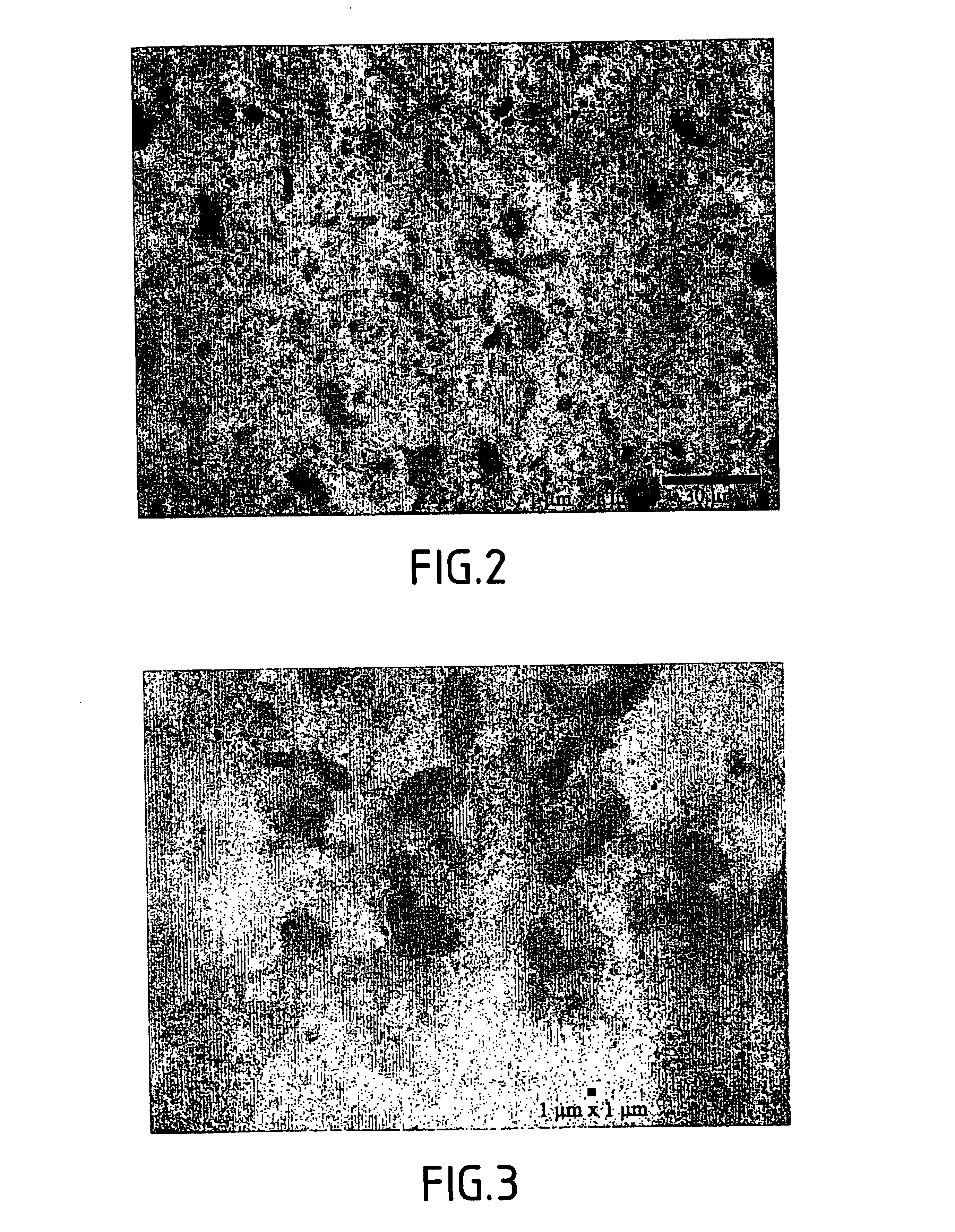
[0182] The results of evaluation of the stability and uniform distribution of the dispersion obtained are shown in Table 1.

example 2

Denoted by XF004 in Table 1

[0183] 9.8 mg of bare carbon nanotubes were mixed with 20.3 mg of pigment and 6.1 mg of polymer by dry grinding in a ball mill.

[0184] The weight ratio nanotubes / pigment / polymer is 1 / 2.07 / 0.62.

[0185] 5000.0 mg of xylene are added to this mixture and the whole is mixed by bath sonication for 2×15 minutes.

[0186] The results of evaluation of the stability and uniform distribution of the dispersion obtained are shown in Table 1.

example 3

Denoted by XF005 in Table 1

[0187] 9.9 mg of bare carbon nanotubes were mixed with 1.0 mg of pigment and 6.8 mg of polymer by dry grinding in a ball mill.

[0188] The weight ratio nanotubes / pigment / polymer is 1 / 0.1 / 0.69.

[0189] 5035.0 mg of xylene are added to this mixture and the whole is mixed by bath sonication for 2×15 minutes.

[0190] The results of evaluation of the stability and uniform distribution of the dispersion obtained are shown in Table 1.


PUM

PropertyMeasurementUnit
Diameteraaaaaaaaaa
Diameteraaaaaaaaaa
Weight ratioaaaaaaaaaa

Abstract

The present invention relates to a device comprising at least one type of conjugated polymer and at least one type of particular tubular nanostructure. The invention relates mainly to a device comprising at least one type of conjugated polymer (functioning as an electron donor) and at least one type of tubular nanostructure (functioning as an electron acceptor), said tubular nanostructure comprising at least one complexed pigment on its surface. The device is proposed in particular for forming a photovoltaic cell.

Description

[0001] Device comprising at least one type of tubular nanostructure having at least one complex pigment on the surface thereof [0002] The invention relates to carbon nanotubes, to dispersions of these nanotubes, to composite materials and to articles made of a composite material comprising these carbon nanotubes. It further relates to the processes for the manufacture of such products. [0003] The present invention further relates to a device comprising at least one type of conjugated polymer and at least one type of particular tubular nanostructure. Different devices are proposed for forming a photovoltaic cell. STATE OF THE ART [0004] Since their discovery in 1991 (Iijima, S., Nature 354 (1991) 56-58), carbon nanotubes have quickly aroused the interest of researchers due to their unique properties. Their exceptional elasticity and tensile strength, their very good electrical and thermal conductivities and their chemical and thermal stabilities open up numerous potential implication...

Claims


Application Information

Patent Timeline
IPC IPC(8): H01L31/00C01B31/02H01L51/00H01L51/30
CPCB82Y10/00H01L27/304H01L51/0035H01L51/0036H01L51/0037H01L51/0038Y02E10/549H01L51/0049H01L51/005H01L51/0077H01L51/0078H01L51/424H01L51/4253H01L51/0048H10K30/53H10K85/111H10K85/1135H10K85/114H10K85/225H10K85/221H10K85/60H10K85/113H10K85/311H10K85/30H10K30/20H10K30/352H10K30/30
Inventor SAINTE CATHERINE, JULIENFRAYSSE, JEROME
Owner NANOLEDGE
Why Eureka
Try Eureka