Method to synchronize stereographic hardware to sequential color rendering apparatus

a color rendering apparatus and stereographic hardware technology, applied in the field of synchronizing stereographic hardware and sequential color rendering apparatus, can solve the problems of stray light leakage through seams, affecting affecting so as to improve the depth of field, improve the quality of the image, and reduce the effect of flicker

Inactive Publication Date: 2007-06-21
IBM CORP
View PDF47 Cites 31 Cited by
  • Summary
  • Abstract
  • Description
  • Claims
  • Application Information

AI Technical Summary

Benefits of technology

[0028] The shortcomings of the prior art are overcome and additional advantages are provided through the use of a sensor system employing one or more photosensors, with appropriate color filters on each sensor to detect the position of the color wheel at any instant. In another embodiment of the present invention, we provide a new method for extracting synchronization information at the light output of the projection apparatus, without modifying the filter wheel or its drive electronics. This solution compensates for the use of multiple color filter segments and white balance segments, can be adapted to any type of projection system, and provides higher quality images with less flicker and better depth of field than previous approaches.

Problems solved by technology

This creates various problems because as the polarizer rotates it causes the polarization transmission axis of the image to rotate also.
This results in ghosting of the image; the viewer will perceive a blurred mixture of left and right eye views sometimes, rather than a clear image resulting from total separation of the left and right eye views.
Despite the use of guiding lenses and optics within these systems, there can be relatively high levels of stray light reflected throughout the interior of the projector package.
Some stray light can also leak in from outside the projector through seams in the case.
This stray light becomes a problem when we use an optical sensor to synchronize the projector polarizer filter wheel with a stereoscopic imaging device.
Stray light can cause false triggering of the sensors and disrupt the required frequency and phase synchronization.
This synchronization is not necessarily achieved simply by accessing the electronic signals used to control the color filter wheel.
While it is possible to generate stereographic, three dimensional imaging from personal computers and other digital video devices, existing video game consoles lack the standard interface required for generating a video synchronization signal.
Thus, the projection lenses and other optics may corrupt the polarization encoded image signal.
This prior art will not work for all types of video input such as line interleaved video streams.
This approach does not use DLP technology and it is not extensible to DLP technology since it requires special film processing techniques.
These solutions also tend to be expensive, are only practical for a limited number of users at one time, and tend to induce eye strain after prolonged use.
As a totality, the prior art techniques require modifications internal to the projector filter wheel, and do not provide implementations using legacy systems.
This means that special optics must be used, and polarization sensitive coatings must be avoided, thereby increasing both the complexity and implementation cost.

Method used


Image

  • Method to synchronize stereographic hardware to sequential color rendering apparatus
  • Method to synchronize stereographic hardware to sequential color rendering apparatus
  • Method to synchronize stereographic hardware to sequential color rendering apparatus

Examples


Embodiment Construction

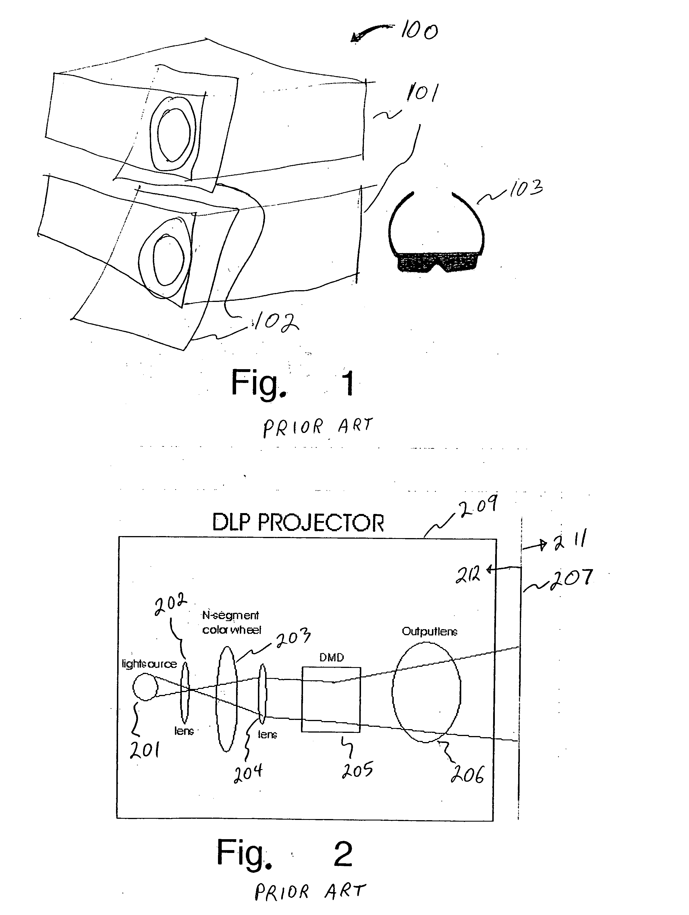
[0055] For generating three dimensional (“3D”) images, two separate two dimensional (“2D”) images representing two lines of sight of a 3D scene are required—one 2D image viewed by each of a person's eyes exclusive to each eye. The apparatus illustrated in FIG. 1 is a traditional 3D projection system that uses a two projection device to simultaneously overlap the images and achieve a stereoscopic display.

[0056] With reference to FIG. 1, there is illustrated a prior art three dimensional projection system 100. This prior art utilizes two separate projectors 101 each projecting an identical scene but each with a slightly different perspective corresponding to the different perspectives between a person's left eye and right eye lines of sight. Polarized glass (or other material) filters 102 are placed in the paths of the projected light beams from each of the two projectors. The polarization angles of these filters are offset 90° from each other. In order for a viewer to perceive a thr...


PUM


Abstract

A method and apparatus for extracting synchronization information at the output of a projection apparatus, without modifying its rotating color segmented filter wheel or drive electronics. Three photodiodes, each with a different principle color filter, is placed at the projector output to detect output of the different colors in the filter wheel. An exclusive OR circuit is used to detect white light passing through the filter wheel.

Description

CROSS REFERENCES TO RELATED APPLICATIONS [0001] U.S. patent applications Ser. No. 11 / ______, entitled “Lumen optimized stereo projector using a plurality of polarizing filters”; and [0002] Ser. No. 11 / ______, entitled “Stereographic projection apparatus with passive eyewear utilizing a continuously variable polarizing element”; and [0003] Ser. No. 11 / ______, entitled “Universal stereographic trigger peripheral for electronic equipment”; and [0004] Ser. No. 11 / ______, entitled “Method and system for synchronizing opto-mechanical filters to a series of video synchronization pulses and derivatives thereof”; and [0005] Ser. No. 11 / ______, entitled “Noise Immune Optical Encoder for High Ambient Light Projection Imaging Systems”; and [0006] Ser. No. 11 / ______, entitled “Signal Synthesizer for Periodic Acceleration and Deceleration of Rotating Optical Devices”, all filed concurrently herewith are assigned to the same assignee hereof and contain subject matter related, in certain respect, t...

Claims


Application Information

Patent Timeline
Patent Type & Authority Applications(United States)
IPC IPC(8): G03B21/00H04N13/363
CPCG03B21/14H04N13/0438H04N13/0459H04N13/0497G03B33/08G03B35/16H04N13/341H04N13/363H04N13/398
Inventor DECUSATIS, CASIMER M.TRIFILO, TIMOTHY M.
Owner IBM CORP
Why Eureka
Try Eureka