
Method for producing membrane-electrode assembly for fuel cell

Inactive Publication Date: 2007-06-21
HONDA MOTOR CO LTD
View PDF2 Cites 46 Cited by
  • Summary
  • Abstract
  • Description
  • Claims
  • Application Information

AI Technical Summary

Benefits of technology

[0022] The immersion of the electrode-membrane assembly in a water tank to introduce water into the electrolyte membrane and thereby cause the solvent to flow out from the electrolyte membrane may occur as a method of removing the solvent from the electrolyte membrane. However, the positive and negative electrode diffusion layers forming the opposite sides of the electrode-membrane assembly are water-repellent and are sparingly permeable to water in a liquid state. Even if the electrode-membrane assembly may be immersed in a water tank, therefore, the positive and negative electrode diffusion layers prevent water in a liquid state from entering the electrolyte membrane and make it difficult to remove the solvent from the electrolyte membrane.
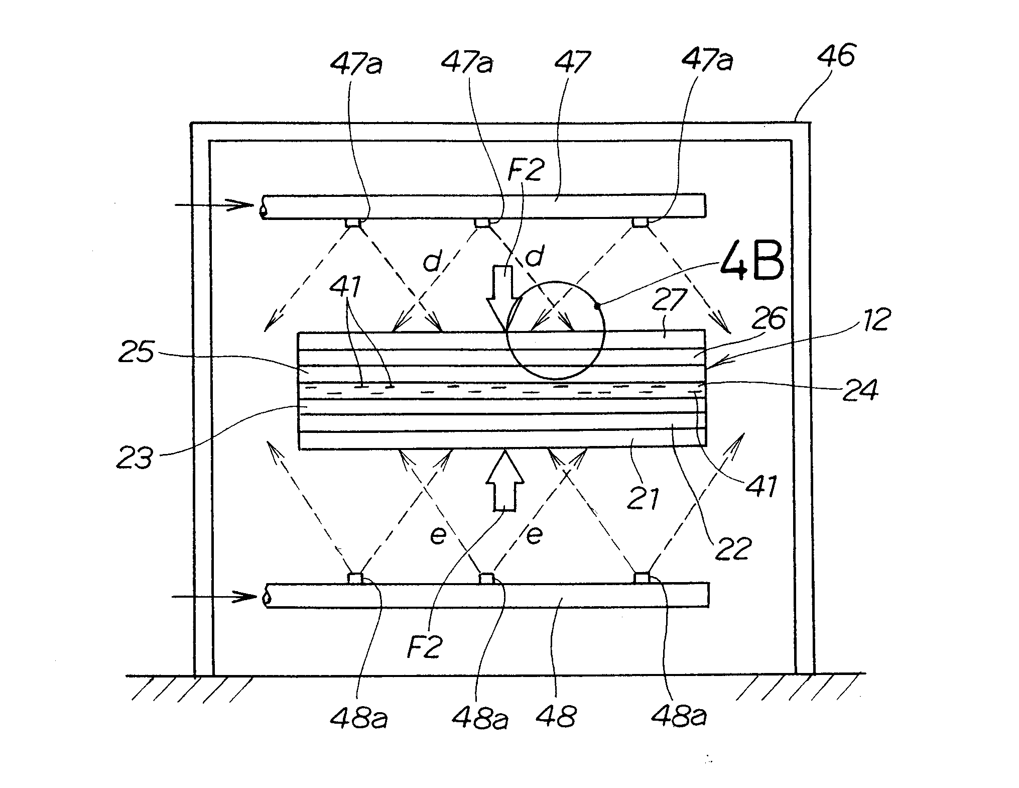
[0025] When vapor is used for the removal of the solvent as stated, vapor passes through the positive and negative electrode diffusion layers and is introduced into the electrolyte membrane. The vapor introduced into the electrolyte membrane makes it possible to remove the solvent from the electrolyte membrane smoothly. Accordingly, the electrode-membrane assembly has an elevated power generating performance, while maintaining its productivity.
[0027] The elevation of saturation vapor pressure is preferable for vapor (water vapor) to remove the solvent from the electrolyte membrane satisfactorily. The elevation of the saturation vapor pressure makes it necessary to maintain at a high level the temperature of the environment in which vapor treatment is performed. However, if the environment temperature is higher than the decomposition temperature of the hydrocarbon solid polymer, the hydrocarbon solid polymer is decomposed. Therefore, the removal of the solvent from the electrolyte membrane is performed at a temperature not exceeding the decomposition temperature of the hydrocarbon solid polymer. This makes it possible to remove the solvent from the electrolyte membrane without having the hydrocarbon solid polymer decomposed and thereby raise the power generating performance of the electrode-membrane assembly.
[0034] The absorption of expansion or contraction of the electrode membrane and the positive and negative electrode layers prevents the separation or cracking of the electrode membrane and the positive and negative electrode layers.
[0035] The solvent used in the method of the present invention is preferably at least one selected from N-methyl-2-pyrrolidone, dimethylacetamide, dimethyl sulfoxide, N,N-dimethylformamide and γ-butyrolactone. These solvents are suitable for the mass production of electrolyte membranes, as they are relatively easily available.
[0036] These solvents have a higher boiling point than that of water. However, the solvent in the electrolyte membrane can be removed properly by the vapor introduced into the electrolyte membrane, even if the solvent temperature may not be raised to its boiling point. Therefore, they are easy to use as the solvent for the electrolyte membrane.

Problems solved by technology

Even if the electrode-membrane assembly may be immersed in a water tank, therefore, the positive and negative electrode diffusion layers prevent water in a liquid state from entering the electrolyte membrane and make it difficult to remove the solvent from the electrolyte membrane.
The positive and negative electrode diffusion layers prevent the permeation of water in a liquid state, but do not prevent the permeation of water vapor.
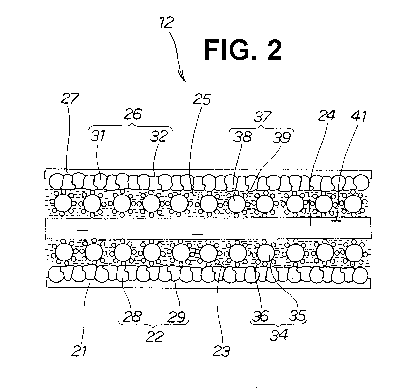
As the pores of the positive and negative electrode diffusion layers are larger in diameter than gases, and smaller than liquids, the positive and negative electrode diffusion layers prevent the permeation of water in a liquid state, but do not prevent the permeation of water vapor.

Method used


Image

  • Method for producing membrane-electrode assembly for fuel cell
  • Method for producing membrane-electrode assembly for fuel cell
  • Method for producing membrane-electrode assembly for fuel cell

Examples


Embodiment Construction

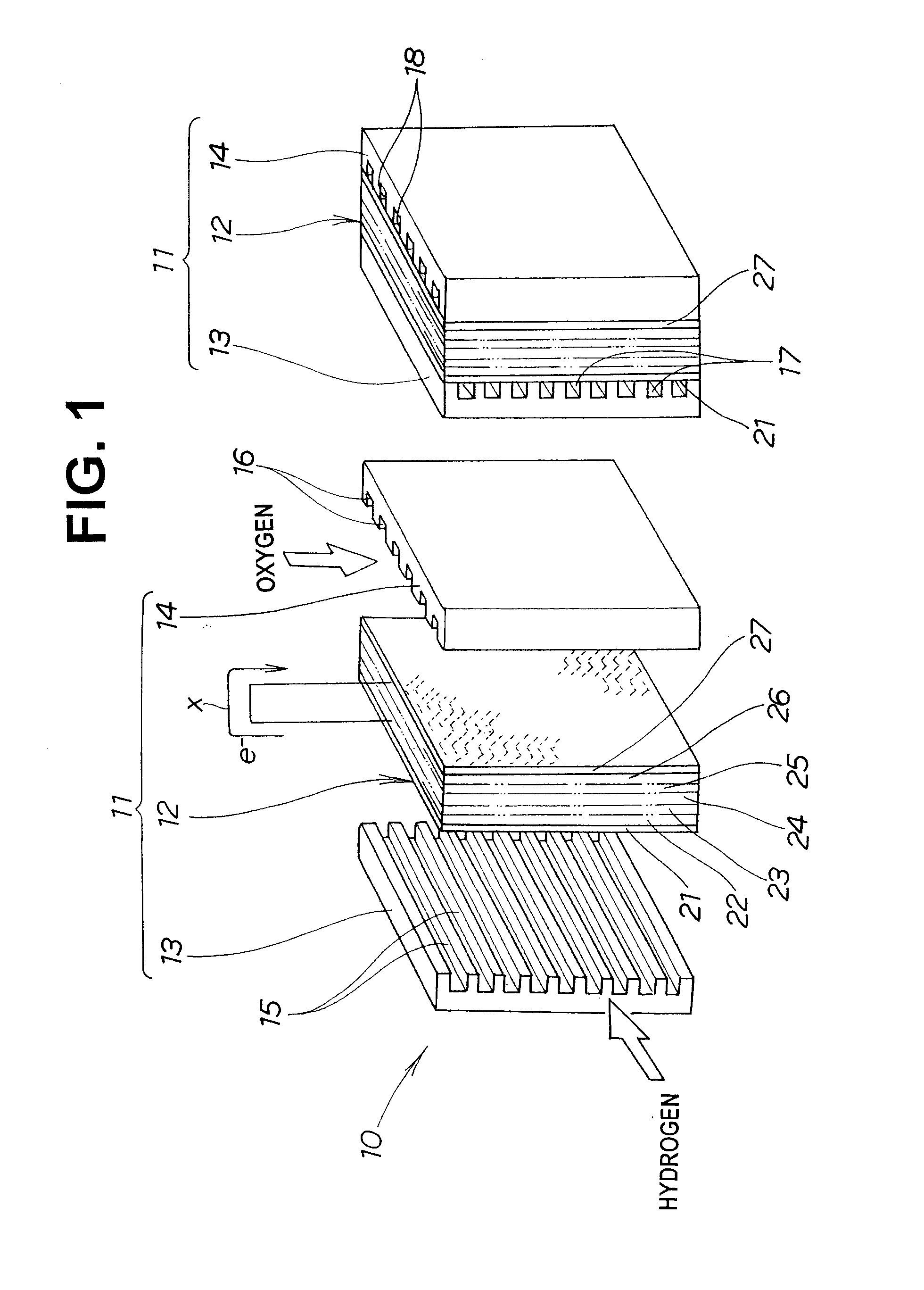
[0049]FIG. 1 shows a fuel cell unit 10 including an electrode-membrane assembly for a fuel cell according to the present invention.

[0050] The fuel cell unit 10 is composed of a plurality of fuel cells 11 (two in the example shown in FIG. 1).

[0051] Each fuel cell 11 has a negative electrode separator 13 and a positive electrode separator 14 on the opposite sides, respectively, of an electrode-membrane assembly 12 for a fuel cell.

[0052] The electrode-membrane assembly 12 is composed of a negative electrode diffusion layer 21, a negative electrode substrate layer 22, a negative electrode layer 23, an electrolyte membrane 24, a positive electrode layer 25, a positive electrode substrate layer 26 and a positive electrode diffusion layer 27 superposed on one another.

[0053] The negative electrode diffusion layer 21 and the positive electrode diffusion layer 27 define the opposite sides of the electrode-membrane assembly 12.

[0054] The negative electrode separator 13 is superposed on th...


PUM


Abstract

Disclosed is a method for removing a solvent (41) in an electrolyte membrane (24) as a constituent of a membrane-electrode assembly (12) used in a fuel cell. The membrane-electrode assembly is arranged in a water vapor, and the water vapor is introduced into the electrolyte membrane by being transmitted through diffusion layers (21, 27) respectively on positive / negative electrode sides. The solvent in the electrolyte membrane is removed by the thus-introduced water vapor. This removal of the solvent is performed at temperatures which are not higher than the decomposition temperature of the hydrocarbon solid polymer.

Description

TECHNICAL FIELD [0001] The present invention relates to a method of producing an electrode-membrane assembly used in a fuel cell and more particularly to a method of producing an electrode-membrane assembly having an electrolyte membrane of a hydrocarbon solid polymer. BACKGROUND ART [0002]FIG. 11 shows a known electrode-membrane assembly for a fuel cell. [0003] Referring to FIG. 11, the electrode-membrane assembly 100 comprises a negative electrode diffusion layer 101, a negative electrode substrate layer 102 laid on the negative electrode diffusion layer 101, a negative electrode layer 103 laid on the negative electrode substrate layer 102, an electrolyte membrane 104 laid on the negative electrode layer 103, a positive electrode layer 105 laid on the electrolyte membrane 104, a positive electrode substrate layer 106 laid on the positive electrode layer 105 and a positive electrode diffusion layer 107 laid on the positive electrode substrate layer 106. [0004] A method of removing ...

Claims


Application Information

Patent Timeline
IPC IPC(8): B05D5/12H01M4/88H01M8/10H01M8/02
CPCH01M4/8807H01M4/881H01M4/8882H01M8/0245H01M8/1004H01M8/1086Y02E60/521Y02P70/50Y02E60/50
Inventor OKIYAMA, GENDATE, TOMOKONAKAO, YASUHIROKAKUTANI, OSAMU
Owner HONDA MOTOR CO LTD
Learn More