
Integrated brake, suspension and wheel system

a technology of suspension and wheel, which is applied in the direction of braking drum, fluid actuated drum brake, transportation and packaging, etc., can solve the problems of system increase, high cost, and large amount of kinetic energy, and achieve high conductivity, low weight, and high thermal capacity

Inactive Publication Date: 2007-06-28
ARCONIC INC
View PDF18 Cites 21 Cited by
  • Summary
  • Abstract
  • Description
  • Claims
  • Application Information

AI Technical Summary

Benefits of technology

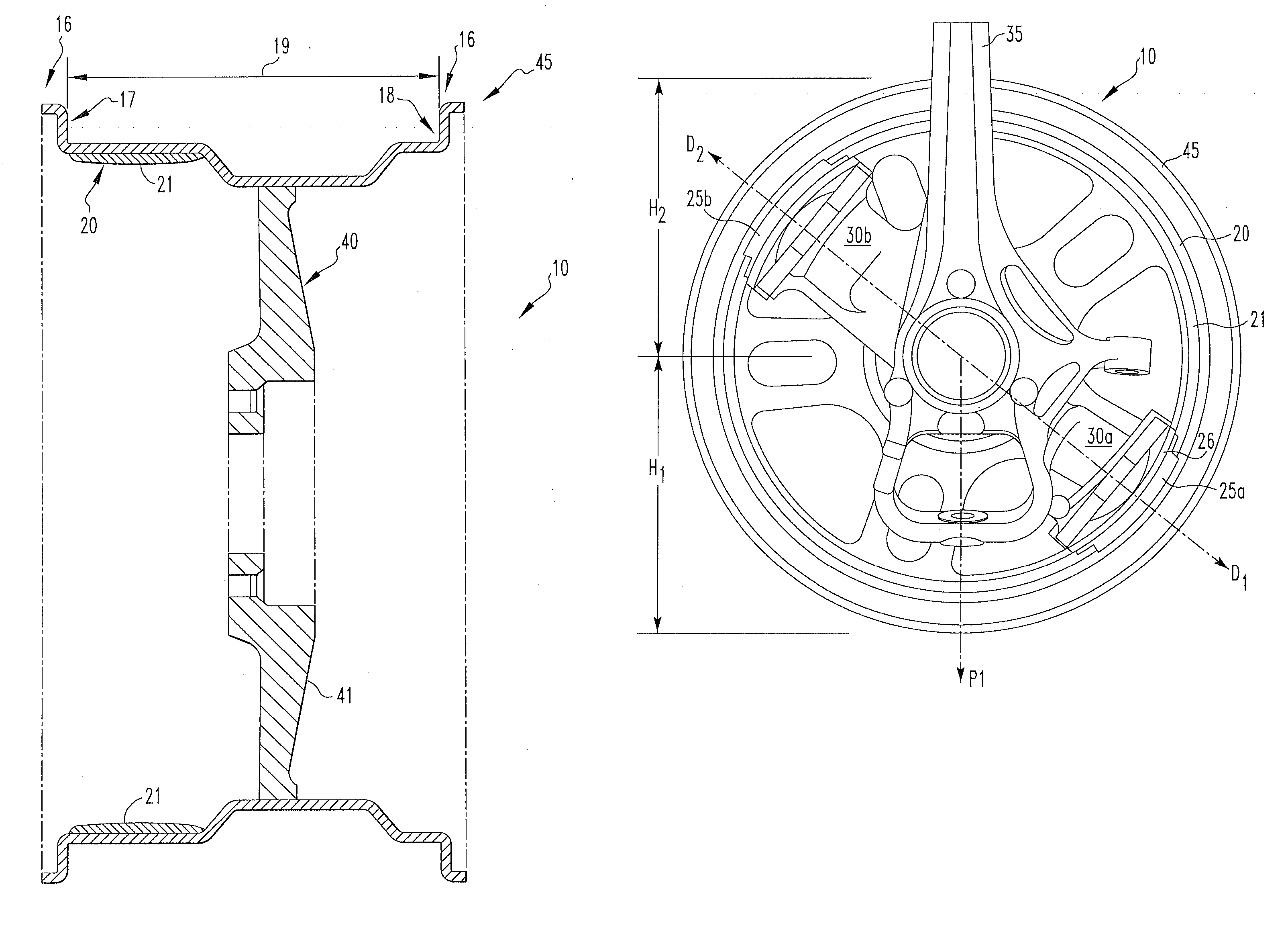
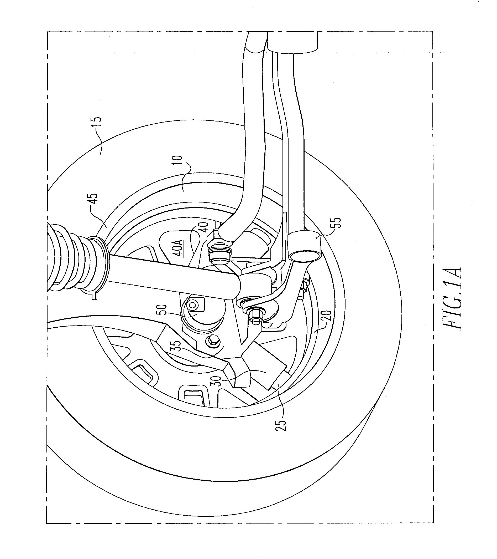
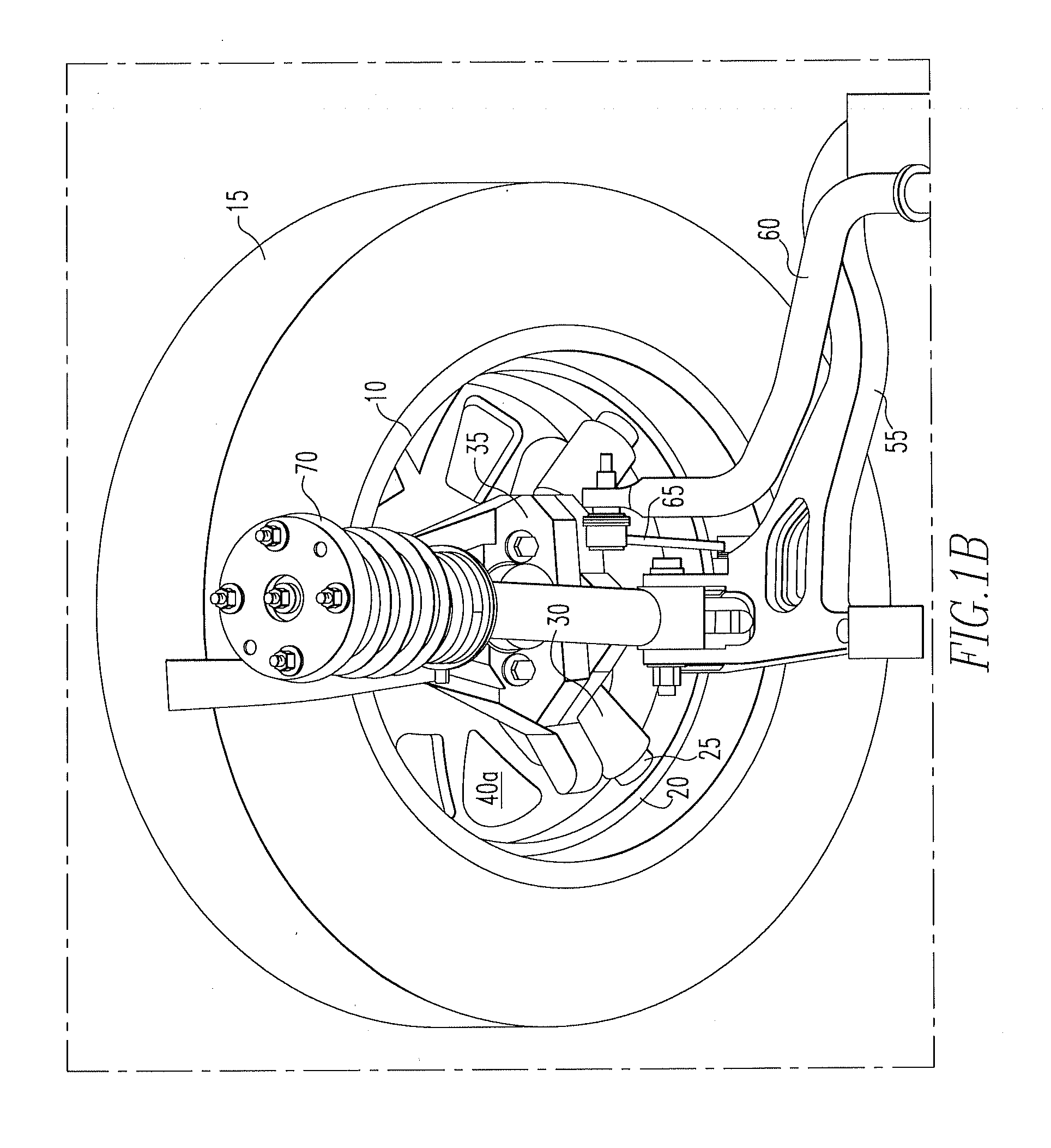
[0007] In one embodiment, a brake system is provided, in which the braking surfaces are positioned along an interior surface of the rim portion of at least one wheel. In one embodiment, the inventive brake system integrates at least one of the functions of the wheel, brake and the suspension taking advantage of at least one of aluminum's low weight, high thermal capacity, and high conductivity in dissipating heat while stopping the vehicle.
[0019] In one embodiment the brake surface may be disposed on at least a portion of the interior surface of the rim portion of a wheel composed of aluminum. In one embodiment the brake surface may be provided by a friction-wear coating having at least one of good resistance to wear, good high temperature stability and thermal conductivity, good adhesion to aluminum, good machinability and solution potentials and coefficients of thermal expansion close to that of the aluminum substrate onto which the coating will be applied. In one embodiment, the brake surface may be provided by a friction wear coating composed of a blend of aluminum and stainless steel. In one embodiment, the friction-wear coating may be composed of a blend of Aluminum Association 1100 wrought alloy and AISI 308 stainless steel. In one embodiment, the brake surface may be composed of a ceramic or carbide or organic metallic composites.

Problems solved by technology

Modern vehicles are of significant mass and travel at significant speeds, hence producing a large amount of kinetic energy that must be dissipated quickly by conversion to heat in the brake system with minimal effort by the driver.
Although, these systems increase the safety and handling quality of the vehicle, the systems also increase the vehicle's weight, complexity and cost.
By increasing the mass of the brake system the vehicles kinetic energy is increased at speed, wherein the increased mass also disadvantageously decreases the vehicles handling abilities and fuel efficiency.
One disadvantage of conventional brake systems is that heat generation, the mechanism by which the kinetic energy of the moving car is dissipated, has an adverse effect on the braking system's effectiveness and reliability.

Method used


Image

  • Integrated brake, suspension and wheel system
  • Integrated brake, suspension and wheel system
  • Integrated brake, suspension and wheel system

Examples


Embodiment Construction

[0034] Detailed embodiments of the present invention are disclosed herein; however, it is to be understood that the disclosed embodiments are merely illustrative of the invention that may be embodied in various forms. In addition, each of the examples given in connection with the various embodiments of the invention are intended to be illustrative, and not restrictive. Further, the figures are not necessarily to scale, some features may be exaggerated to show details of particular components. Therefore, specific structural and functional details disclosed herein are not to be interpreted as limiting, but merely as a representative basis for teaching one skilled in the art to variously employ the present invention. In the accompanying drawings, like and / or corresponding elements are referred to by like reference numbers.

[0035] Referring to FIGS. 1a and 1b, a brake and suspension system is provided comprising a wheel 10 with a sealing surface having provisions for mounting a tire 15 ...


PUM

PropertyMeasurementUnit
Frictionaaaaaaaaaa

Abstract

A brake system including a suspension component housing at least one actuation piston to reversibly extend a brake pad; and a wheel that is in rotational engagement to the suspension component, the wheel having a rim portion with an interior surface that is contacted by the brake pad of at least one actuation piston when in an extended position.

Description

CROSS REFERENCE TO RELATED APPLICATIONS [0001] The present invention is a continuation in part and claims the benefit of U.S. Pat. Application Ser. No. 11 / 300,241, filed Dec. 14, 2005, the whole contents and disclosure of which is incorporated by reference as is fully set forth herein.FIELD OF THE INVENTION [0002] The present invention relates to brake systems. In one embodiment, the present invention relates to brake systems for automotive applications. BACKGROUND OF THE INVENTION [0003] Many different types of vehicle brake systems have evolved over the last 100 years ranging from pure mechanical devices to more sophisticated systems incorporating hydraulic and / or electromagnetic principals to brake or assist in braking the vehicle. [0004] In all cases the kinetic energy of the moving vehicle must be absorbed by the braking system, wherein the kinetic energy is typically absorbed by being converted into heat. Modern vehicles are of significant mass and travel at significant speeds...

Claims


Application Information

Patent Timeline
IPC IPC(8): F16D51/00
CPCB60B21/08C23C4/00C23C30/00F16D51/10F16D51/14C23C24/04F16D2051/003F16D2065/1336F16D2065/138F16D2121/02F16D2250/0046F16D65/22
Inventor SEKSARIA, DINESH C.KAUFOLD, ROGERMURPHY, THOMAS J.SOKOL, RICHARD A.
Owner ARCONIC INC
Learn More