Hydrogen generation method
- Summary
- Abstract
- Description
- Claims
- Application Information
AI Technical Summary
Benefits of technology
Problems solved by technology
Method used
Image
Examples
example 1
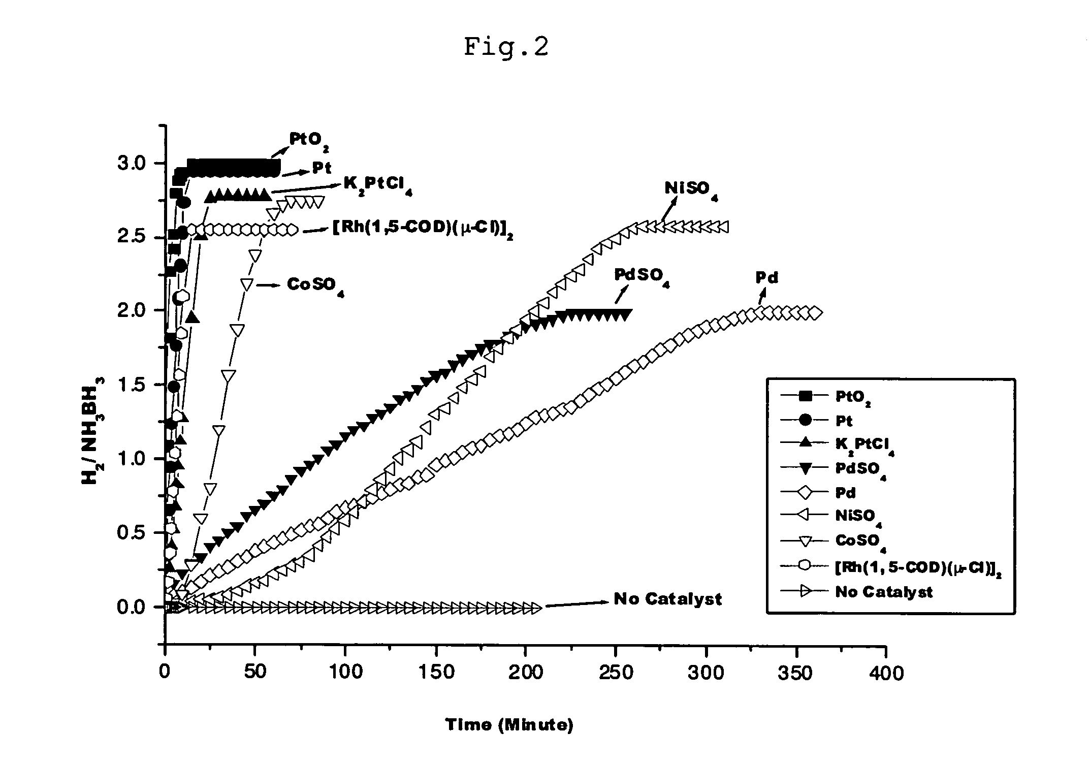
[0081]4.0 mg of platinum oxide (PtO2) powder was placed in a 30 ml two-necked flask. A gas burette was connected to one neck and a 50 ml dropping funnel with pressure-equalizing arm was connected to the other neck. 15 ml of aqueous solution in which 50 mg of ammonia borane (NH3BH3, 90% purity) was dissolved was placed in the dropping funnel.
[0082] The inside of the system was evacuated with a vacuum pump, and then filled with argon gas. The aqueous ammonia borane solution was introduced from the dropping funnel into the two-necked flask, and stirring was conducted at room temperature. One minute after stirring was started, it was observed that 39 ml of gas had been released; two minutes after, 65 ml; 5 minutes after, 87 ml; 10 minutes after, 105 ml; and 30 minutes after, 107 ml.
[0083] Gas chromatographic (GC) and mass spectral (MS) analyses showed that the gas released was hydrogen. The amount of hydrogen released was 3 moles per mole of ammonia borane (NH3BH3) as a starting mater...
example 2
[0085]4.0 mg of platinum (Pt) powder was placed in a 30 ml two-necked flask. A gas burette was connected to one neck and a 50 ml dropping funnel with pressure-equalizing arm was connected to the other neck. 15 ml of aqueous solution in which 50 mg of ammonia borane (NH3BH3, 90% purity) was dissolved was placed in the dropping funnel.
[0086] The inside of the system was evacuated with a vacuum pump, and then filled with argon gas. The aqueous ammonia borane solution was introduced from the dropping funnel into the two-necked flask, and stirring was conducted at room temperature. One minute after stirring was started, it was observed that 12.5 ml of gas had been released; two minutes after, 23.5 ml; 5 minutes after, 53.5 ml; 10 minutes after, 97.5 ml; and 30 minutes after, 105 ml.
[0087] Gas chromatographic (GC) and mass spectral (MS) analyses showed that the released gas was hydrogen. The amount of hydrogen released was 3 moles per mole of ammonia borane (NH3BH3) as a starting materi...
example 3
[0089] After the reaction of Example 2 was complete, platinum (Pt) powder was collected by filtration and placed in a 30 ml two-necked flask. A gas burette was connected to one neck and a 50 ml dropping funnel with pressure-equalizing arm was connected to the other neck. 15 ml of aqueous solution in which 50 mg of ammonia borane (NH3BH3, 90% purity) was dissolved was placed in the dropping funnel.
[0090] The inside of the system was evacuated with a vacuum pump, and then filled with argon gas. The aqueous ammonia borane solution was introduced from the dropping funnel into the two-necked flask, and stirring was conducted at room temperature. One minute after stirring was started, it was observed that 11 ml of gas had been released; two minutes after, 22 ml; 5 minutes after, 51 ml; 10 minutes after, 97 ml; and 30 minutes after, 105 ml.
[0091] Gas chromatographic (GC) and mass spectral (MS) analyses showed that the released gas was hydrogen. The amount of hydrogen released was 3 moles...
PUM
 Abstract
Description
Claims
Application Information
 - R&D
- Intellectual Property
- Life Sciences
- Materials
- Tech Scout
- Unparalleled Data Quality
- Higher Quality Content
- 60% Fewer Hallucinations
Browse by: Latest US Patents, China's latest patents, Technical Efficacy Thesaurus, Application Domain, Technology Topic, Popular Technical Reports.
© 2025 PatSnap. All rights reserved.Legal|Privacy policy|Modern Slavery Act Transparency Statement|Sitemap|About US| Contact US: help@patsnap.com


