Method of reducing contamination by providing an etch stop layer at the substrate edge

a technology of etch stop and substrate edge, which is applied in the manufacturing of semiconductor/solid-state devices, basic electric elements, electrical equipment, etc., can solve the problems of copper and other devices, tool contamination even exacerbated, and process tools contaminated, so as to reduce the probability of substrate and/or tool contamination, reduce the probability of etch damage of the substrate, and reduce the effect of etch damag

Inactive Publication Date: 2007-07-05
ALSEPHINA INNOVATIONS INC
View PDF5 Cites 15 Cited by
  • Summary
  • Abstract
  • Description
  • Claims
  • Application Information

AI Technical Summary

Benefits of technology

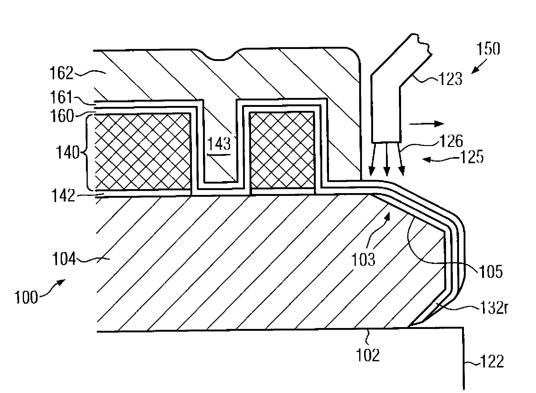
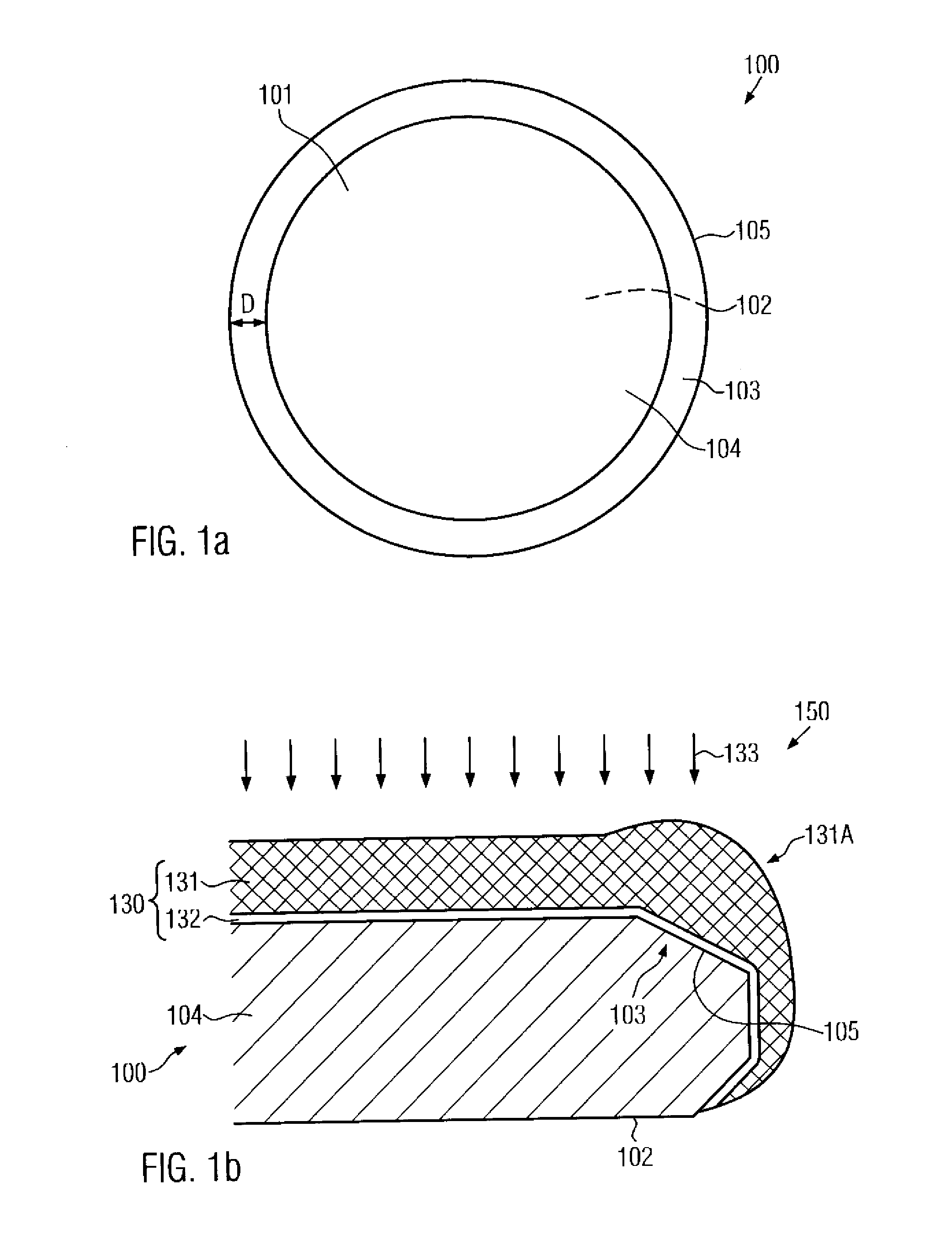
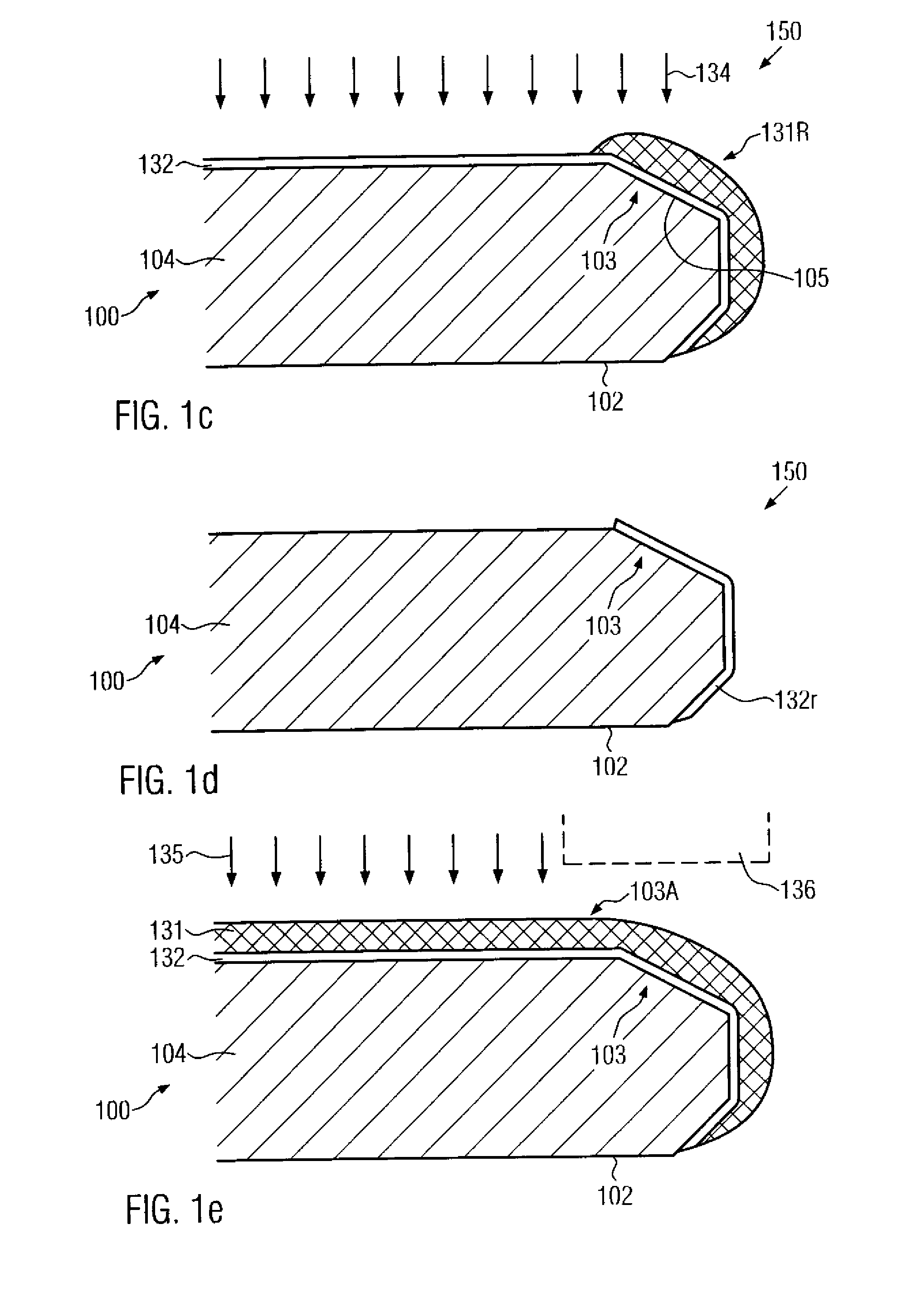
[0013]Generally, the present invention is directed to a technique that enables the formation of metallization layers of semiconductor devices, and in illustrative embodiments of semiconductor devices including copper-based metal lines embedded in a low-k dielectric material, with a reduced probability for substrate and / or tool contamination. For this purpose, an additional etch stop layer is selectively formed at the bevel region of the substrate prior to forming a metallization structure so as to enable the reduction of the delamination of dielectric material and / or metallic material during the formation of a metallization layer in that at least the dielectric material is substantially completely removed from the bevel region of the substrate. Moreover, any further unwanted materials created during the further processing of the substrate may also be efficiently removed by a spatially selective bevel etch process substantially without exposing the substrate material. Hence, any barrier material or metal may be effectively removed. In this way, the formation of a mechanically unstable dielectric layer stack in the bevel region of the substrate may be substantially avoided. In some illustrative embodiments, the etch stop layer may be selectively formed at the bevel in an early manufacturing state, thereby enabling the removal of any unwanted materials substantially throughout the entire manufacturing process in a highly compatible manner.
[0014]According to one illustrative embodiment of the present invention, a method comprises selectively forming a first etch stop layer above a bevel region of a substrate, wherein the substrate has a central region adjacent to the bevel region for receiving circuit elements therein. The method further comprises forming a dielectric layer stack for a metallization layer above the substrate. Moreover, a portion of at least one layer of the dielectric layer stack is removed from the bevel region by selectively applying an etchant to the bevel region while using the first etch stop layer to reduce etch damage of the substrate. Finally, the dielectric layer stack is patterned in the central region to receive at least one of a via and a trench.

Problems solved by technology

Although copper exhibits significant advantages when compared to aluminum as being the typical metallization metal for the last decade, semiconductor manufacturers have been somewhat reluctant to introduce copper in the production, owing to copper's ability to readily diffuse in silicon and silicon dioxide.
Moreover, even when being present in very small amounts, copper may significantly modify the electrical characteristics of silicon and, thus, the behavior of circuit elements, such as transistors and the like.
Furthermore, any contamination of process tools, such as transport means, transport containers, robot arms, wafer chucks and the like, must be effectively restricted, since even minute amounts of copper deposited on the back side of a substrate may lead to diffusion of the copper into sensitive device areas.
The problem of copper and other device and tool contamination is even exacerbated when low-k dielectric materials are employed in combination with copper to form metallization layers, owing to the reduced mechanical stability of the low-k dielectrics.
Since at least some of the deposition processes used in fabricating semiconductors may not be efficiently restricted to the “active” substrate area, a stack of layers or material residues may also be formed at the substrate edge region, including the bevel, thereby generating a mechanically unstable layer stack owing to process non-uniformities at the substrate edge and especially at the bevel of the substrate.
During the further production and substrate handling processes, material such as copper, barrier material and / or the dielectrics may delaminate and significantly affect these processes, thereby negatively affecting production yield and tool integrity.
The deposition of the barrier layer may be accomplished by chemical vapor deposition (CVD) or physical vapor deposition (PVD), wherein a deposition of the barrier material may not be efficiently restricted to the active substrate area by presently established deposition techniques.
Consequently, the barrier material may also be deposited at the substrate bevel and partially at the back side of the substrate, thereby forming, in combination with residues of the dielectric material that may not be efficiently removed by the previous etch processes for patterning the dielectric layer, a layer stack of reduced mechanical stability.
Although reactor vessels for the electrochemical deposition, such as electroplating reactors or electroless plating reactors, may be designed such that substantially no copper is deposited at the substrate edge, the preceding seed layer deposition process may nevertheless result in a significant deposition of unwanted copper at the substrate edge region.
This is frequently achieved by chemical mechanical polishing (CMP), wherein material fragments, such as copper pieces, may “flake off,” owing to the reduced stability of the metallization layer stack, especially at the substrate bevel.
The copper-containing material flakes and other material flakes comprised of dielectric material and / or barrier material, for instance liberated during the CMP process, may then re-deposit at unwanted substrate regions or may affect the CMP process of subsequent substrates.
During the further processing of the substrate, a contamination, mainly caused by the delamination at the substrate edge, may occur and may especially adversely affect the so-called back-end process flow, in which contact pads and solder bumps are formed.
Although the removal of unwanted copper from the substrate edge reduces the risk of copper contamination of subsequent processes, it turns out, however, that a significant reduction of production yield, especially in the manufacturing sequence for higher metallization layers and in the back-end process flow, is still observable.

Method used


Image

  • Method of reducing contamination by providing an etch stop layer at the substrate edge
  • Method of reducing contamination by providing an etch stop layer at the substrate edge
  • Method of reducing contamination by providing an etch stop layer at the substrate edge

Examples


Embodiment Construction

[0020]Illustrative embodiments of the invention are described below. In the interest of clarity, not all features of an actual implementation are described in this specification. It will of course be appreciated that in the development of any such actual embodiment, numerous implementation-specific decisions must be made to achieve the developers' specific goals, such as compliance with system-related and business-related constraints, which will vary from one implementation to another. Moreover, it will be appreciated that such a development effort might be complex and time-consuming, but would nevertheless be a routine undertaking for those of ordinary skill in the art having the benefit of this disclosure.

[0021]The present invention will now be described with reference to the attached figures. Various structures, systems and devices are schematically depicted in the drawings for purposes of explanation only and so as to not obscure the present invention with details that are well ...


PUM

PropertyMeasurementUnit
diametersaaaaaaaaaa
diametersaaaaaaaaaa
diametersaaaaaaaaaa

Abstract

By providing an etch stop layer selectively at the bevel, at least one additional wet chemical bevel etch process may be performed prior to or during the formation of a metallization layer without affecting the substrate material. Hence, the dielectric material, especially the low-k dielectric material, may be reliably removed from the bevel prior to the formation of any barrier and metal layers. The etch stop layer may be formed at an early manufacturing stage so that a bevel etch process may be performed at any desired stage of the formation of circuit elements.

Description

BACKGROUND OF THE INVENTION[0001]1. Field of the Invention[0002]Generally, the present invention relates to the fabrication of integrated circuits, and, more particularly, to the formation of metallization layers and contaminations related thereto in subsequent processes.[0003]2. Description of the Related Art[0004]Semiconductor devices are typically formed on substantially disc-shaped substrates made of any appropriate material. The majority of semiconductor devices including highly complex electronic circuits are currently, and in the foreseeable future will be, manufactured on the basis of silicon, thereby rendering silicon substrates and silicon-containing substrates, such as silicon-on-insulator (SOI) substrates, viable carriers for forming semiconductor devices, such as microprocessors, SRAMs, ASICs (application specific ICs) and the like. The individual integrated circuits are arranged in an array form, wherein most of the manufacturing steps, which may add up to 500-1000 and...

Claims


Application Information

Patent Timeline
Patent Type & Authority Applications(United States)
IPC IPC(8): H01L21/00
CPCH01L21/02087H01L21/76877H01L21/76801H01L21/6708
Inventor RICHTER, RALFLETZ, TOBIASSCHUEHRER, HOLGER
Owner ALSEPHINA INNOVATIONS INC
Why Eureka
Try Eureka