
Method of fabricating photo mask

a technology of photo mask and mask body, which is applied in the direction of photomechanical equipment, instruments, originals for photomechanical treatment, etc., can solve the problems of affecting affecting the lithography technique, and not correcting the layout, so as to increase the accuracy of opc process and improve the productivity of opc process

Active Publication Date: 2007-07-12
SAMSUNG ELECTRONICS CO LTD
View PDF24 Cites 26 Cited by
  • Summary
  • Abstract
  • Description
  • Claims
  • Application Information

AI Technical Summary

Benefits of technology

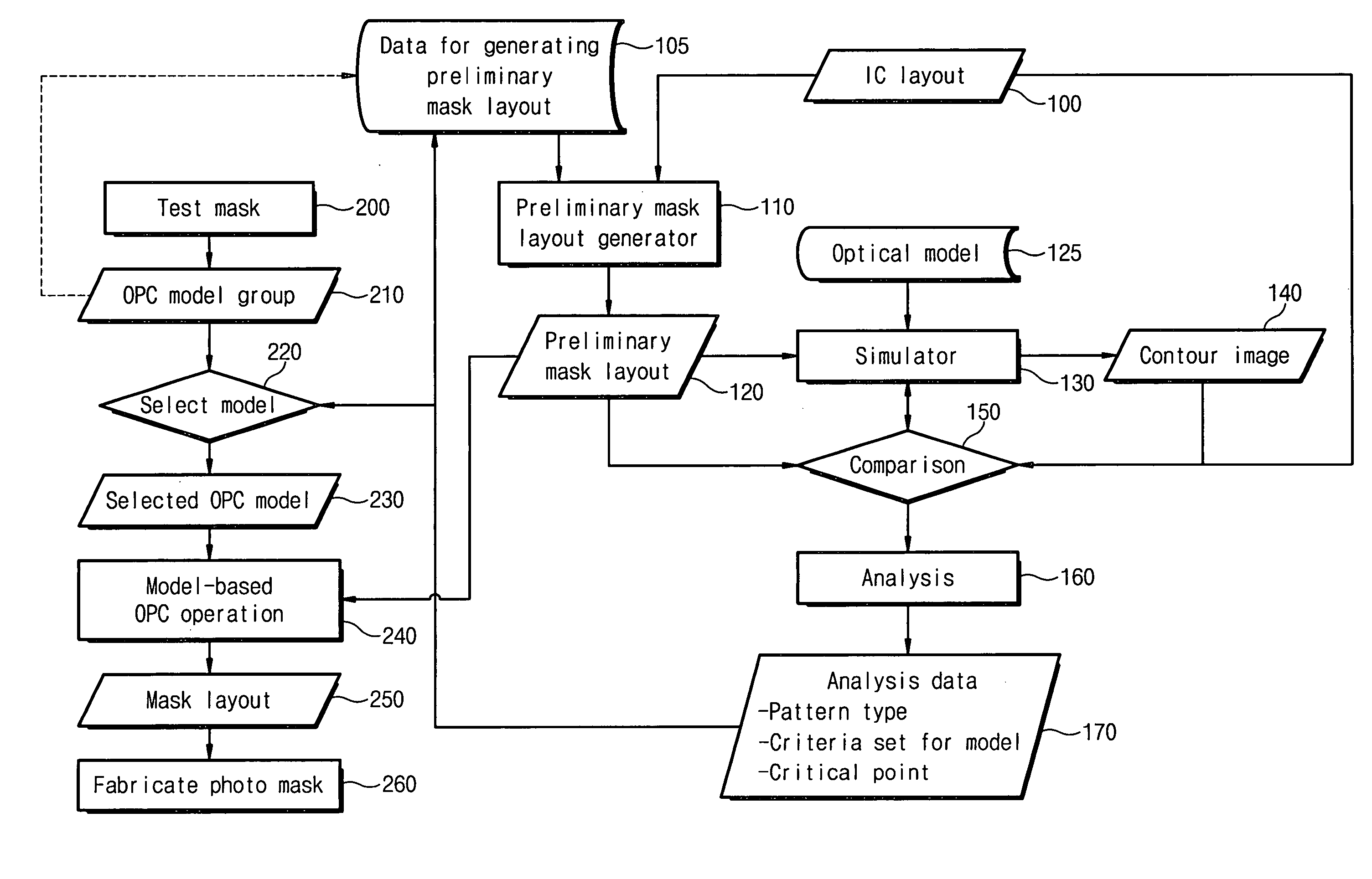
[0019] Example embodiments provide a method of fabricating a photo mask that may select an improved or optimized optical proximity correction (OPC) model without depending on the engineers' experience. Example embodiments also provide a method of fabricating a photo mask that leads to an improvement in the productivity of an OPC process. Further, example embodiments provide a method of fabricating a photo mask that may increase the accuracy of an OPC process.

Problems solved by technology

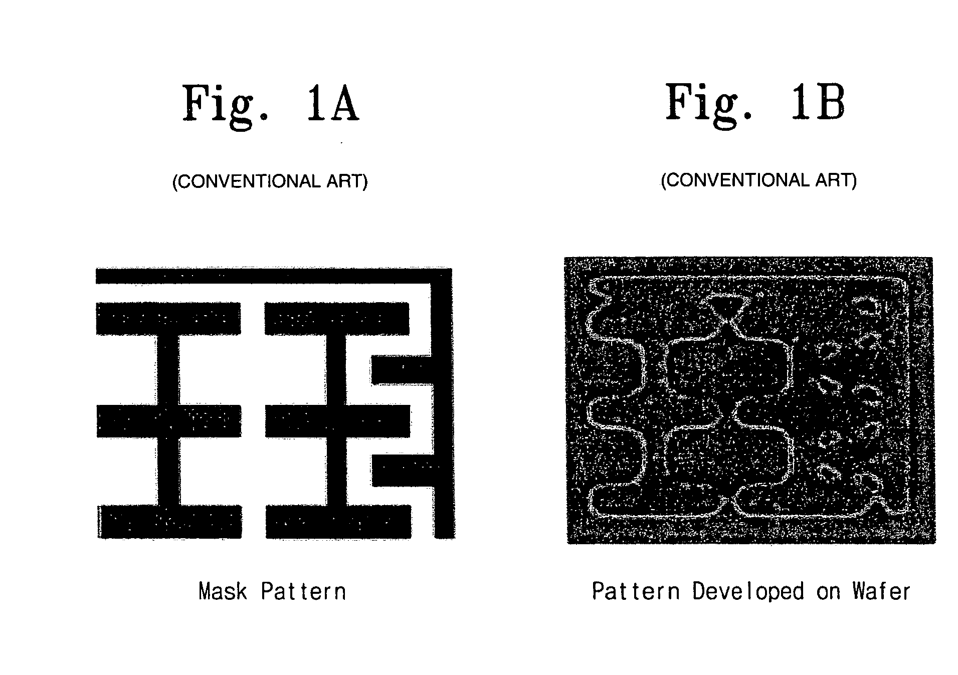
However, as the integration density of semiconductor devices increase, the size of mask patterns may approximate to the wavelength of a light source, resulting in the lithography technique being affected by diffraction and / or interference of light.
Thus, a distortion of an image due to the OPE becomes worse.
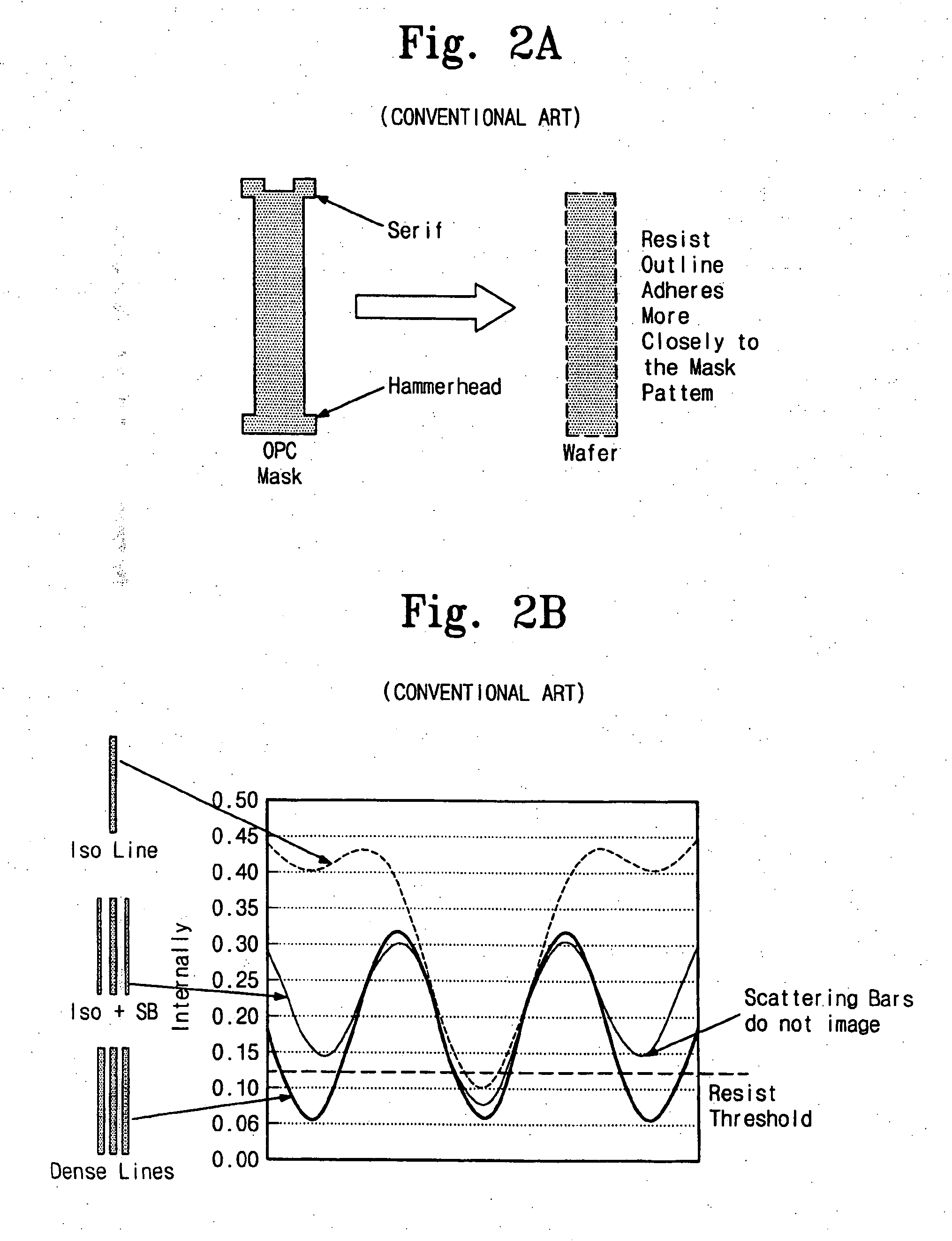
Rule-based OPC techniques may not correct the layout based on simulation results, a pattern formed on a wafer may not be as precise as required.
However, it may be possible that many trial and error iterations are needed to apply a rule-based method to a new lithography process adopting different lithography apparatuses and / or a new illumination technique.
This re-fabrication of the photo mask causes an increase in fabrication cost and a delay in the date of delivery.
In this case, the OPC model 15 may be inappropriate for the OPC operation 30 and a failure in the photo mask may be induced.
Therefore, when an unnecessarily strict OPC model is selected, the productivity of the OPC operation 30 may deteriorate.
Because the appropriateness of the OPC model 15 depends upon the engineers' experience, this conventional OPC method may not reduce or prevent an unnecessarily strict OPC method from being selected.
However, because the sampled region may be selected by engineers' experience, the dependence of the appropriateness of the OPC model 15 on the engineers' experience may not be completely overcome.
Thus, this OPC method also may not overcome the dependence of the appropriateness of the OPC model on the engineers' experience.
As a consequence, it may be difficult to improve the productivity of an OPC process.

Method used


Image

  • Method of fabricating photo mask
  • Method of fabricating photo mask
  • Method of fabricating photo mask

Examples


Embodiment Construction

[0043] Reference will now be made in detail to example embodiments, examples of which are illustrated in the accompanying drawings. However, example embodiments are not limited to the embodiments illustrated hereinafter, and the embodiments herein are rather introduced to provide easy and complete understanding of the scope and spirit of example embodiments. In the drawings, the thicknesses of layers and regions are exaggerated for clarity.

[0044] It will be understood that when an element or layer is referred to as being “on,”“connected to” or “coupled to” another element or layer, it may be directly on, connected or coupled to the other element or layer or intervening elements or layers may be present. In contrast, when an element is referred to as being “directly on,”“directly connected to” or “directly coupled to” another element or layer, there are no intervening elements or layers Like reference numerals refer to like elements throughout. As used herein, the term “and / or” incl...


PUM


Abstract

Provided is a method of fabricating a photo mask. The method includes preparing a model group including optical proximity correction (OPC) models and generating a preliminary mask layout using an integrated circuit (IC) layout. A contour image may be produced from the preliminary mask layout through a simulation using an optical model. Subsequently, the preliminary mask layout may be compared with the contour image and the comparison result may be analyzed to produce analysis data for providing criteria used in selecting an OPC model. An OPC model suitable for the preliminary mask layout may be selected from the model group based on the analysis data. An OPC process may be performed on the preliminary mask layout using the selected OPC model to generate a mask layout.

Description

PRIORITY STATEMENT [0001] This application claims priority under 35 USC § 119 to Korean Patent Application No. 2005-0102471, filed on Oct. 28, 2005, in the Korean Intellectual Property Office (KIPO), the entire contents of which are herein incorporated by reference. BACKGROUND [0002] 1. Field [0003] Example embodiments relate to a method of fabricating a photo mask that may improve or optimize optical proximity correction (OPC). [0004] 2. Description of the Related Art [0005] In general, a lithography technique used for fabrication of semiconductor devices involves transferring a pattern formed on a photo mask to a wafer through an optical lens. However, as the integration density of semiconductor devices increase, the size of mask patterns may approximate to the wavelength of a light source, resulting in the lithography technique being affected by diffraction and / or interference of light. Because an optical system for projecting an image may function as a low-pass filter, a photore...

Claims


Application Information

Patent Timeline
IPC IPC(8): G06F17/50G03F1/00G21K5/00
CPCG03F1/36G03F1/144G03F7/70441
Inventor SUH, SUNG-SOOKANG, YOUNG-SEOGKIM, IN-SUNG
Owner SAMSUNG ELECTRONICS CO LTD
Learn More