Capacitive ultrasonic transducer, production method thereof, and capacitive ultrasonic probe

a capacitive ultrasonic transducer and ultrasonic probe technology, applied in electrostatic transducers, precision positioning equipment, chemical vapor deposition coatings, etc., can solve the problems of inconvenient production of capacitive ultrasonic transducers, inconvenient processing and assembly, and reduced center frequency, etc., to achieve efficient acoustic matching with tissue, low effective drive voltage, and easy processing

Inactive Publication Date: 2007-07-19
OLYMPUS CORP
View PDF5 Cites 150 Cited by
  • Summary
  • Abstract
  • Description
  • Claims
  • Application Information

AI Technical Summary

Benefits of technology

[0045] In the above structure, high sound pressure can be obtained in a high frequency domain by using the capacitive ultrasonic transducer according to the present invention. In addition, since it is possible to produce it by a simple production method, it is to aim at cost reduction. Furthermore, since it becomes easy for ultrasonic vibration of a membrane to conduct a tissue, sensitivity improves as a result.
[0047] Because of the above-mentioned structure, the capacitive ultrasonic transducer array with high sensitivity is achieved by not only making the capacitive ultrasonic transducer cells into layered structure, but also making them into the structure of further arranged two-dimensionally in a plane surface of the substrate.
[0049] In the above structure, by using the capacitive ultrasonic transducer according to the present invention, since not only capacitive ultrasonic transducer cells are made into layered structure, but also they are made into the structure of further arranged two-dimensionally in a plane surface of the substrate, it is possible to achieve a capacitive ultrasonic transducer array with high sensitivity.
[0073] In the above structure, by using the capacitive ultrasonic transducer according to the present invention, it is possible to achieve a capacitive ultrasonic probe, which can achieve acoustic matching with a tissue efficiently, has a low effective drive voltage, can be used in a body cavity, is easily processed and assembled, can secure chemical resistance, can reduce loss by a coaxial cable, and is available to the harmonic imaging diagnosis, by using a capacitive ultrasonic transducer.
[0074] The capacitive ultrasonic probe according to the present invention is characterized by forming focusing means of focusing ultrasonic beams structurally by a curvature membrane section made by making the above-mentioned membrane section, which constructs the above-mentioned capacitive ultrasonic transducer, a curvature in a capacitive ultrasonic probe which embeds the capacitive ultrasonic transducer which transmits and receives an ultrasonic wave by vibration of the membrane section. In the above-mentioned structure, by focusing ultrasonic beams structurally by the curvature membrane section, it becomes possible to enlarge intensity of the ultrasonic beams transmitted in simple structure, and hence, it is made to be able to obtain a received signal with a good S / N.

Problems solved by technology

Hence, although enlarging the electrode area W2 enlarges transmitted ultrasonic sound pressure, it causes decrease of the center frequency at the same time, and hence, it was extremely difficult to obtain high sound pressure in a high frequency domain.
In addition, heretofore, production of a capacitive ultrasonic transducer was not easy in an economic aspect.

Method used


Image

  • Capacitive ultrasonic transducer, production method thereof, and capacitive ultrasonic probe
  • Capacitive ultrasonic transducer, production method thereof, and capacitive ultrasonic probe
  • Capacitive ultrasonic transducer, production method thereof, and capacitive ultrasonic probe

Examples


first embodiment

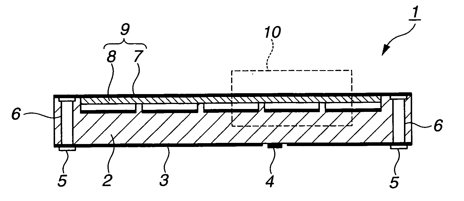
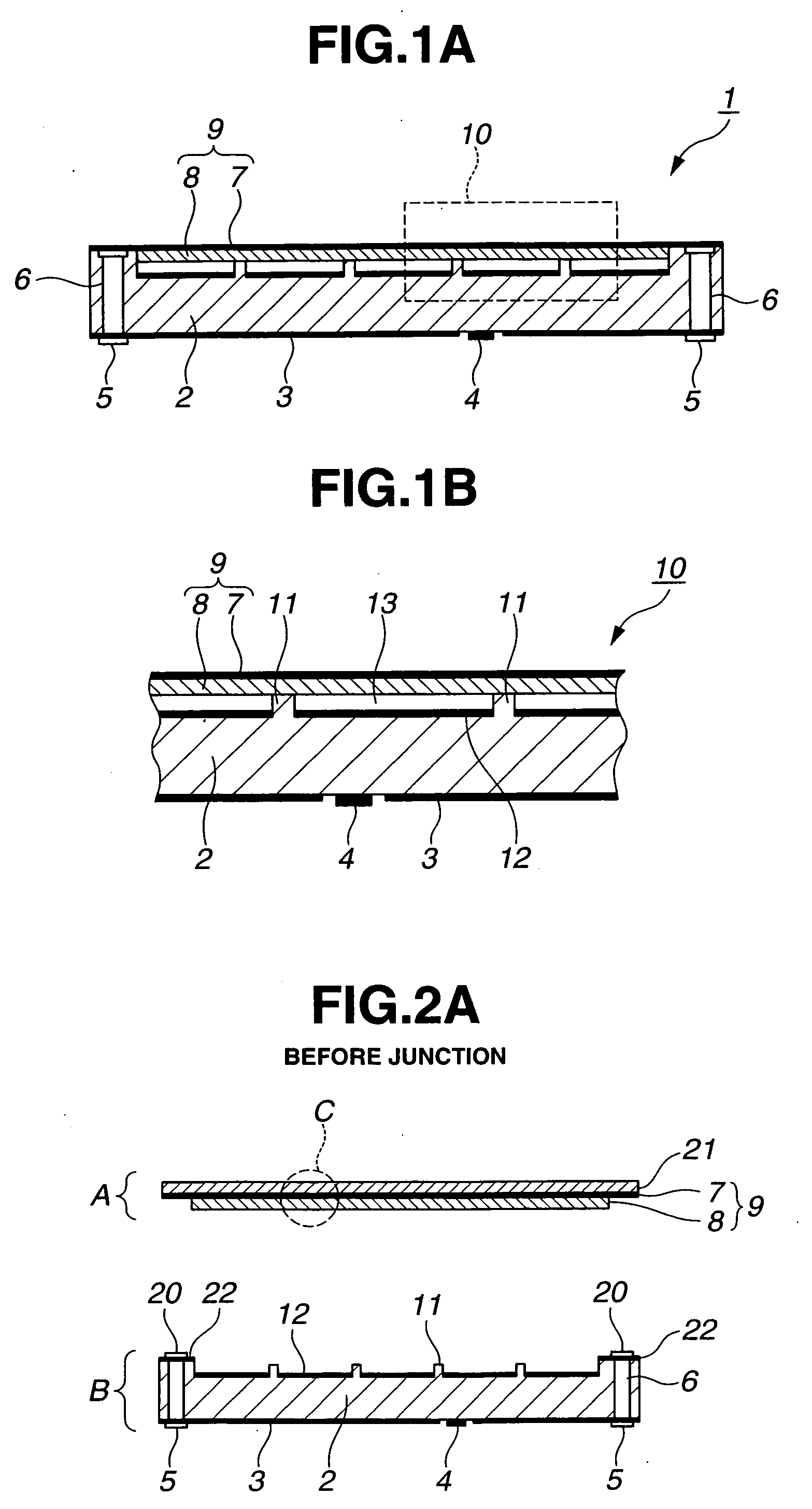
[0156]FIGS. 1A and 1B show basic structure of a capacitive ultrasonic transducer (c-MUT) 1 in this embodiment. FIG. 1A shows a sectional view of the whole capacitive ultrasonic transducer. A unit of the capacitive ultrasonic transducer shown in this FIG. 1A is called an element. In the capacitive ultrasonic transducer, there is a plurality of concavities on a surface of a silicon substrate 2. This one unit is called a cell 10. A membrane 9 covers an upper face of the silicon substrate 2 so as to cover each cell 10. The membrane 9 is a thin film (high dielectric constant film) which comprises an upper electrode 7 and a high dielectric constant oxide layer 8 mentioned later.

[0157] In addition, an insulating layer 3 is provided on a backface of the silicon substrate 2. A backface electrode pad (contact pad) 4 is provided in a part of this insulating layer 3. Interconnect via holes 6 are located in both ends of the silicon substrate 2. A contact pad 5 is provided on one end (a backface...

second embodiment

[0191] An example of a method of fabricating a capacitive ultrasonic transducer with a resin-made cavity forming substrate will be described as the present embodiment. Here, a cavity will hereinafter refer to space between an upper electrode and a lower electrode and does not necessarily have to be hollow. In addition, a concave portion or porosity, which is produced in a process (intermediate stage) prior to becoming a cavity at the time of final fabrication will be also referred to as a cavity.

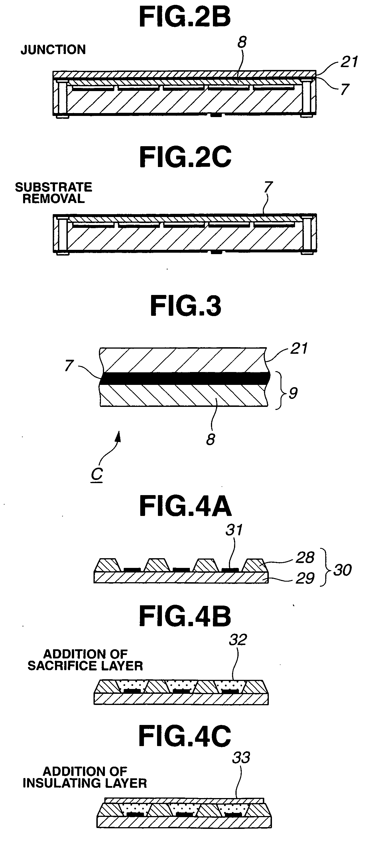
[0192]FIGS. 4A to 4E are drawings showing a fabrication process in the present embodiment. At first, an electrode 31 is formed on a surface of a silicon substrate. Next, on this silicon substrate 29, a supporting portion 28 is formed in a portion where no electrode 31 is disposed (a substrate comprising a silicon substrate 29, a supporting portion 28 and the electrode 31 will be referred to as a resin-made cavity forming substrate 30) (see FIG. 4A). Insulating material selected from the gro...

third embodiment

[0202] A method of fabricating a capacitive ultrasonic transducer with the anode bonding technology will be described in the present embodiment. The anode bonding technology refers to a technology of applying direct voltage of several hundreds of volts under several hundreds of ° C. and employing Si—O covalent bond to stick a silicon surface and a glass surface together. For the present embodiment, a cavity is formed with die forming in use of the technology hereof. Glass is glass including movable ions such as sodium ions and the like.

[0203]FIGS. 5A and 5B are drawings to show fabrication processing for the present embodiment. At first, a silicon substrate 42 subjected to patterning of a plate-like glass substrate 40 provided with a plurality of holes and electrodes 41 thereon is prepared (see FIG. 5A). As to be described below, the glass substrate 40 and the silicon substrate 42 are brought into bonding in the succeeding process and that electrode 41 undergoes patterning on the s...


PUM

PropertyMeasurementUnit
dielectric constantaaaaaaaaaa
voltageaaaaaaaaaa
dielectric constantaaaaaaaaaa

Abstract

It becomes possible to obtain high sound pressure in a high frequency domain by a capacitive ultrasonic transducer which comprises a membrane on which one electrode is formed, a cavity constructed in its backface, and a substrate on which these are mounted and supported and on whose surface an electrode is provided, on a surface in an ultrasonic transmission and reception side, characterized in that the membrane comprises two or more layers, and at least one layer of them comprises a high dielectric constant film.

Description

CROSS REFERENCE TO RELATED APPLICATION [0001] This application is a continuation application of PCT / JP2005 / 010163 filed on Jun. 2, 2005 and claims benefit of Japanese Applications No. 2004-165934 filed in Japan on Jun. 3, 2004, No. 2004-170334 filed in Japan on Jun. 8, 2004, No. 2004-176040 filed in Japan on Jun. 14, 2004 and No. 2004-181521 filed in Japan on Jun. 18, 2004, the entire contents of each of which are incorporated herein by their reference.BACKGROUND OF THE INVENTION [0002] 1. Field of the Invention [0003] The present invention relates to a capacitive ultrasonic transducer, into which a silicon semiconductor substrate is processed using a silicon micromachining technique, and its production method, and to a capacitive ultrasonic probe comprising the capacitive ultrasonic transducer in an end portion of an insertion section inserted into a body cavity. [0004] 2. Description of the Related Art [0005] An ultrasonic diagnosis of diagnosing by radiating an ultrasonic wave in...

Claims


Application Information

Patent Timeline
Patent Type & Authority Applications(United States)
IPC IPC(8): B06B1/06H01L41/00A61B8/00A61B8/12B06B1/02B81B3/00B81C1/00B81C3/00G01N29/04G01N29/24H04R19/00H04R23/00H04R31/00
CPCA61B8/12A61B8/4483A61B8/445G01N29/2437G01N2291/0427B06B1/0292
Inventor ADACHI, HIDEOSAWADA, YUKIHIKOWAKABAYASHI, KATSUHIROMIZUNUMA, AKIKOIMAHASHI, TAKUYAOMURA, ETSUKOOKUNO, YOSHIYUKIOTANI, SHUJIMURAKAMI, MIYUKINEMOTO, KIYOSHISUZUKI, KOZABUROSHIMODA, NAOMI
Owner OLYMPUS CORP
Why Eureka
Try Eureka