Eureka AIR delivers breakthrough ideas for toughest innovation challenges, trusted by R&D personnel around the world.

Method and device for shading in a display system

a display system and display system technology, applied in the direction of identification means, lighting and heating apparatus, instruments, etc., can solve the problems of affecting the shading effect of the display system, the electronics of the display system are sealed against ambient, and the choice of shader materials is limited, so as to improve contrast, specific texture, and stay efficient over a long time

Active Publication Date: 2007-07-19
BARCO NV
View PDF10 Cites 30 Cited by
  • Summary
  • Abstract
  • Description
  • Claims
  • Application Information

AI Technical Summary

Benefits of technology

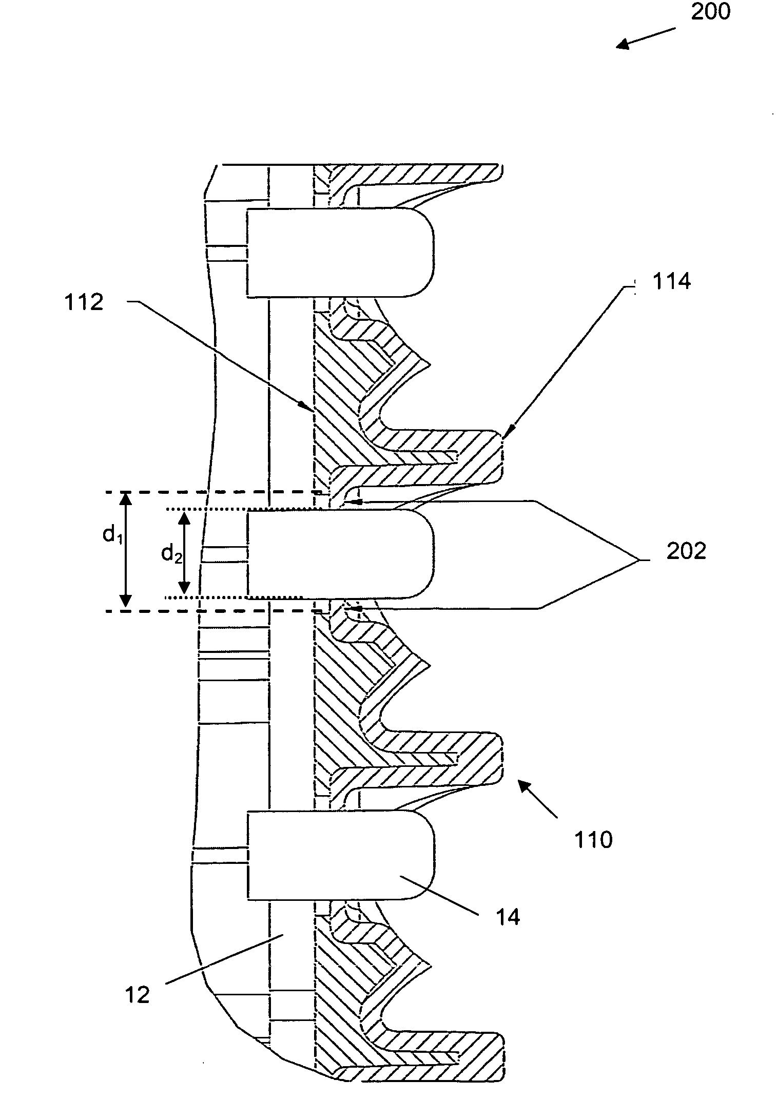
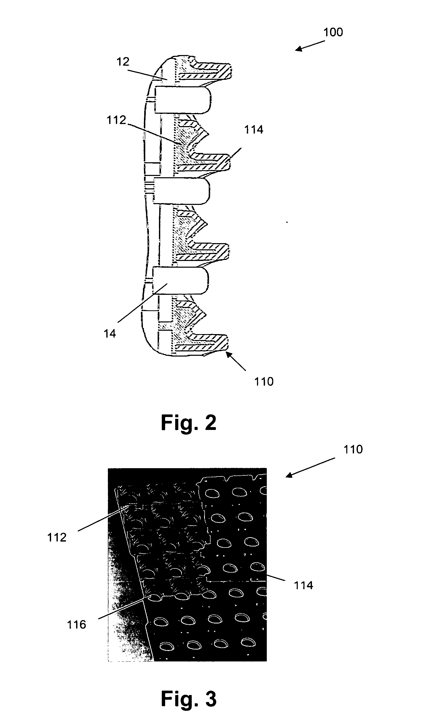
[0006] It is an object of the present invention to provide good apparatus or methods for shading a display system. It is an advantage of embodiments of the present invention to provide apparatus and methods for shading that are efficient and stay efficient over a long time. It is an advantage of embodiments of the present invention that an improved contrast is obtained due to the presence of a shape overlay component that can be moulded and therefore can be given a specific texture, e.g. a matt surface, and a specific shape, e.g. a light-trapping shape. It is also an advantage of embodiments of the present invention that a material with high flexibility can be used, as the overlay material does not need to have the structural properties that the substrate needs for assembly and stability. The latter keeps the material selection open for achieving other goals, such as a high contrast, having a soft material and / or having a material with high dust repulsion. It is furthermore an advantage of embodiments of the present invention that an improved manufacturability is obtained, due to the elimination of the need for solvents, glues and due to the elimination of manual sprays that typically are used in prior-art shader-coating concepts. It is also an advantage of embodiments of the present invention that a mouldable overlay system according to embodiments of the present invention allows the optional use of a soft material leading to a reduction of the possibilities for injury when handling or otherwise coming into contact with the product. The latter may occur in sports markets or rental markets. It is also an advantage of embodiments of the present invention that the overlay material can be optionally used as a water, dust and / or air sealing material on any side of the product.
[0008] In a first aspect, the present invention provides a shading device for shading a display system, the shading device comprising a first component and a second component, the first component being a core component and the second component at least partly covering the core component, wherein the second component is a solid continuous layer having a lower reflectivity than the core component. The second component preferably has an improved long-term black colour experience compared to the core component. With a solid layer is meant a layer which is self-supporting. With a continuous layer is meant a layer which does not comprise discrete separate portions. It is an advantage of embodiments of the present invention that they provide a system that suffers less from flaking off compared to sprayed components.
[0012] According to embodiments of the present invention, the second component may be a layer provided with a microstructure. These microstructures, either regular or irregular, may be produced by roughening a surface, e.g. by laser processing. The present invention includes modifying the roughness of the surface of the second component, e.g. to increase an existing roughness.
[0032] In accordance with a further aspect, the present invention relates to a shading device for shading a display system, the shading device comprising a first component and a second component, the first component being a core component and the second component at least partly covering the core component, wherein the second component is a solid continuous layer being more elastic than the core component. With a solid layer is meant a layer which is self-supporting. With a continuous layer is meant a layer which does not comprise discrete separate portions. The second component may comprise a region with a thickness of at least 0.5 mm. The second component may comprise a region with a thickness of at least 0.7 mm. The second component may comprise a region with a thickness of at least 1 mm. The thickness typically may be the layer thickness. The layer thickness may vary. It is an advantage of embodiments of the present invention that they provide a good environmental protection e.g. to organic solvents and environmental influences such as ultraviolet rays and weathering. The second material may be more easily changed in shape and may be selected to also absorb impacts.
[0036] It is an advantage of embodiments of the present invention that they provide a system that suffers less from environmental problems and that flakes off less compared to sprayed components. It furthermore is an advantage of embodiments according to the present invention that an easily applicable manufacturing technique can be used
[0040] The second component may be made of an antistatic material. The material of the second component may include fillers which provide an antistatic effect. The material of the second component is preferably, black, e.g. matt black. One filler may be carbon in one of its forms, e.g. carbon black. It is an advantage of embodiments of the present invention that they prevent dust attraction, resulting in a longer lifetime of the black colour experience for users and / or viewers of the device. The shader may provide a black background for the light sources to increase contrast while at the same time reducing glaring or reflection effects in sunlight.

Problems solved by technology

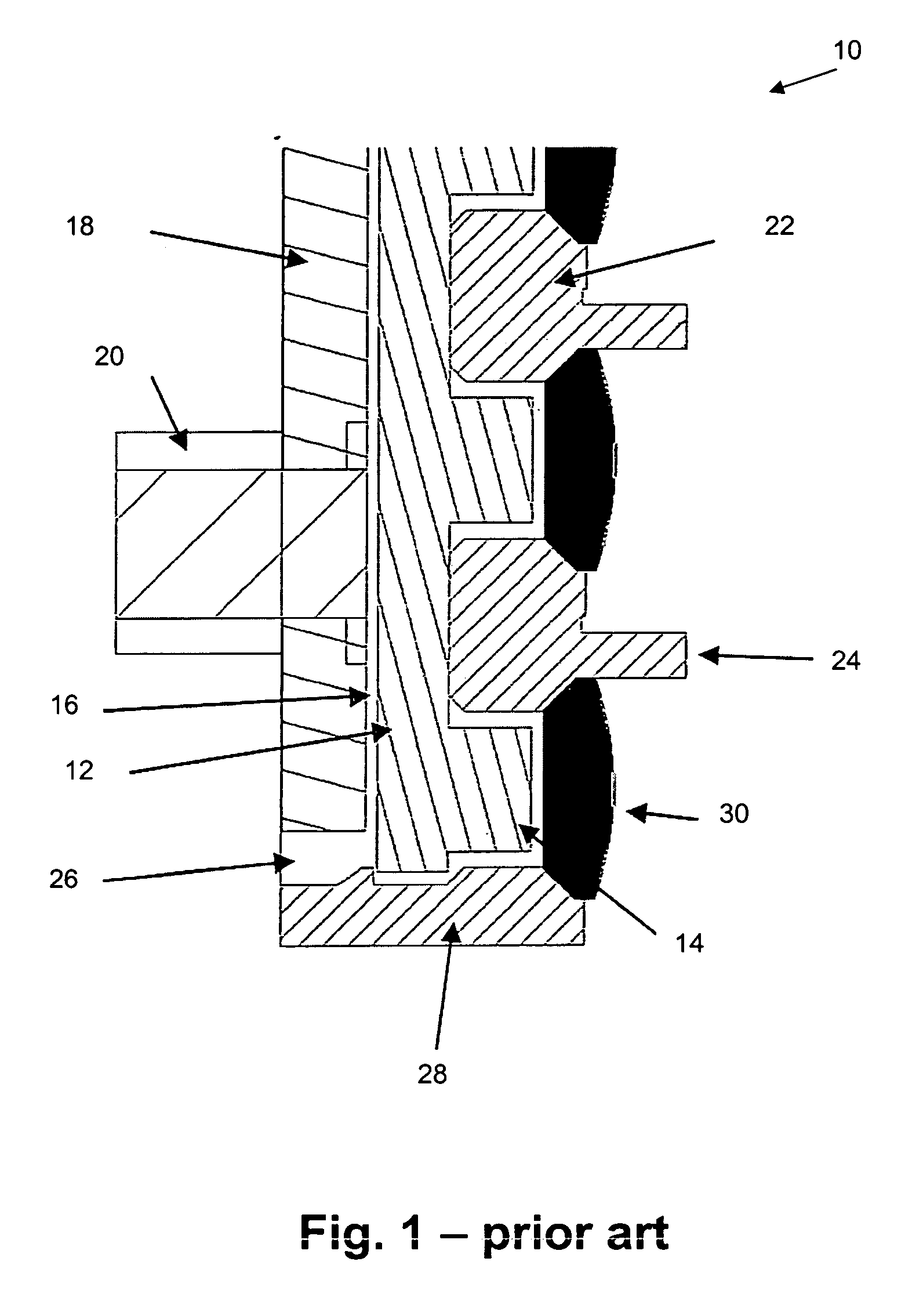
Especially for outdoor applications, although not limited thereto, sealing of the electronics of the display system against ambient, i.e. environmental influence, and shading from other light sources typically is an important issue.
The challenges with the first method is that because of the requirements of assembly and stability, the choice of shader materials is limited.
Polycarbonate or polyamide are the typical choice, but neither of these materials meet all the requirements.
The challenges of the first method also apply to the second method, wherein shaders that poke through the sealing material are used.
Although the sealing material may be dark and mat, thus meeting some of the requirements for a good shader, the sealing material may pose an additional problem.
The sealing material, such as e.g. silicone potting, is often not stable and over time it turns shiny.
Additionally silicone is not mouldable, and it can therefore not be created with any specific texture or shape, e.g. light-trapping shape.

Method used


Image

  • Method and device for shading in a display system
  • Method and device for shading in a display system
  • Method and device for shading in a display system

Examples


first embodiment

[0071] In a first embodiment, the present invention relates to a shading device, e.g. a shading device for use in a display system. The shading device typically comprises a first component that is a core component and a second component that is at least partly covering the core component. The second component typically is a solid continuous layer covering at least a part of the core component. With a solid layer is meant a layer which is self-supporting. With a continuous layer is meant a layer which does not comprise discrete separate portions. The solid continuous layer of the display device is preferred over a fibre based second component (which can attract dust) or a sprayed film (which may flake off). In accordance with embodiments of the present invention, the second component has a lower reflectivity than the first component. Furthermore the second component may be more elastic or more flexible than the core component and / or has a lower hardness than the core component. In ot...

third embodiment

[0087] In a third embodiment, the present invention relates to a shading device according to any of the previous embodiments, whereby the shading device furthermore is adapted for accommodating optical elements in front of the plurality of light source units. The latter may e.g. be an adaptation of the shape of the shading device such that optical elements can be positioned thereon, or may be a kind of clipping, clicking or clamping means for holding optical elements in front of a plurality of light source units. Such optical elements may e.g. be a diffracting element such as a lens or a diffraction grating, or maybe a filter such as a colour filter or a deflection device for directing the light in a direction or range of directions. Such optical elements are typically used for altering the properties of light that propagate through the elements to create desired enhancement effects or to create e.g. optimised full-motion video, magnified images, three-dimensional images, etc. A sha...


PUM


Abstract

A shading device is described for use with a display system. The shading device comprises a first component, typically a rigid component, and a second component. The second component at least partially covers the first component. The second component is a solid continuous film which has a lower reflectivity than the first component. In a particular embodiment, the second component is more elastic or flexible than the first component and / or has a hardness smaller than the first component, and is furthermore adapted such that it can provide a sealing contact with a plurality of light sources. The latter allows using the shading device also as sealing means for sealing electronics and other components of the display system from the ambient of the display system.

Description

TECHNICAL FIELD OF THE INVENTION [0001] The present invention relates to systems, devices and methods for displaying information. More particularly, the present invention relates to systems, devices and methods for shading in display systems, and to such display systems or devices using such shading systems. BACKGROUND OF THE INVENTION [0002] Display systems are often used for displaying information in outdoor applications, such as e.g. for lighting or displaying such as in advertisement of for showing video or other information. Especially for outdoor applications, although not limited thereto, sealing of the electronics of the display system against ambient, i.e. environmental influence, and shading from other light sources typically is an important issue. A shader typically is used to block light from falling on the display system or the light source units thereof and to provide a black background which is non-reflective, e.g. in between the different light source units. Use of a...

Claims


Application Information

Patent Timeline
IPC IPC(8): G02F1/1335
CPCG09F9/30G09F27/008G09F13/22G09F9/33
Inventor MEERSMAN, KARIMBEDDES, AARONNOYELLE, KATRIEN
Owner BARCO NV
Why Eureka
Eureka Blog
Learn More