Fluid transfer member

a technology of transfer member and fluoride, which is applied in the direction of mechanical equipment, other domestic objects, synthetic resin layered products, etc., can solve the problems of pfa tube, inferior thermal stability of pctfe on the occasion of molding, and relatively high liquid chemical permeability, and achieve low chemical liquid permeability and stress cracking. , the effect of low resistan

Active Publication Date: 2007-07-19
DAIKIN IND LTD
View PDF27 Cites 17 Cited by
  • Summary
  • Abstract
  • Description
  • Claims
  • Application Information

AI Technical Summary

Benefits of technology

[0146] The fluid transfer member of the invention, which has the constitution described above, has both stress cracking resistance and low chemical liquid permeability in a balanced manner and, at the same time, can have chemical resistance as well as thermal stability required in the step of molding. BEST MODES FOR CARRYING OUT THE INVENTION
[0147] The following examples illustrate the present invention more specifically. These examples are, however, by no means limitative of the scope of the invention.

Problems solved by technology

However, PFA tubes have a problem, namely they are fairly high in liquid chemical permeability.
However, these tubes still have a problem; namely, when PFA and PCTFE are actually subjected to multilayer extrusion molding, the PCTFE is inferior in thermal stability on the occasion of molding and in stress cracking resistance.
However, there is no concrete disclosure at all about a fluoropolymer comprising both TFE and CTFE as copolymerization components.

Method used

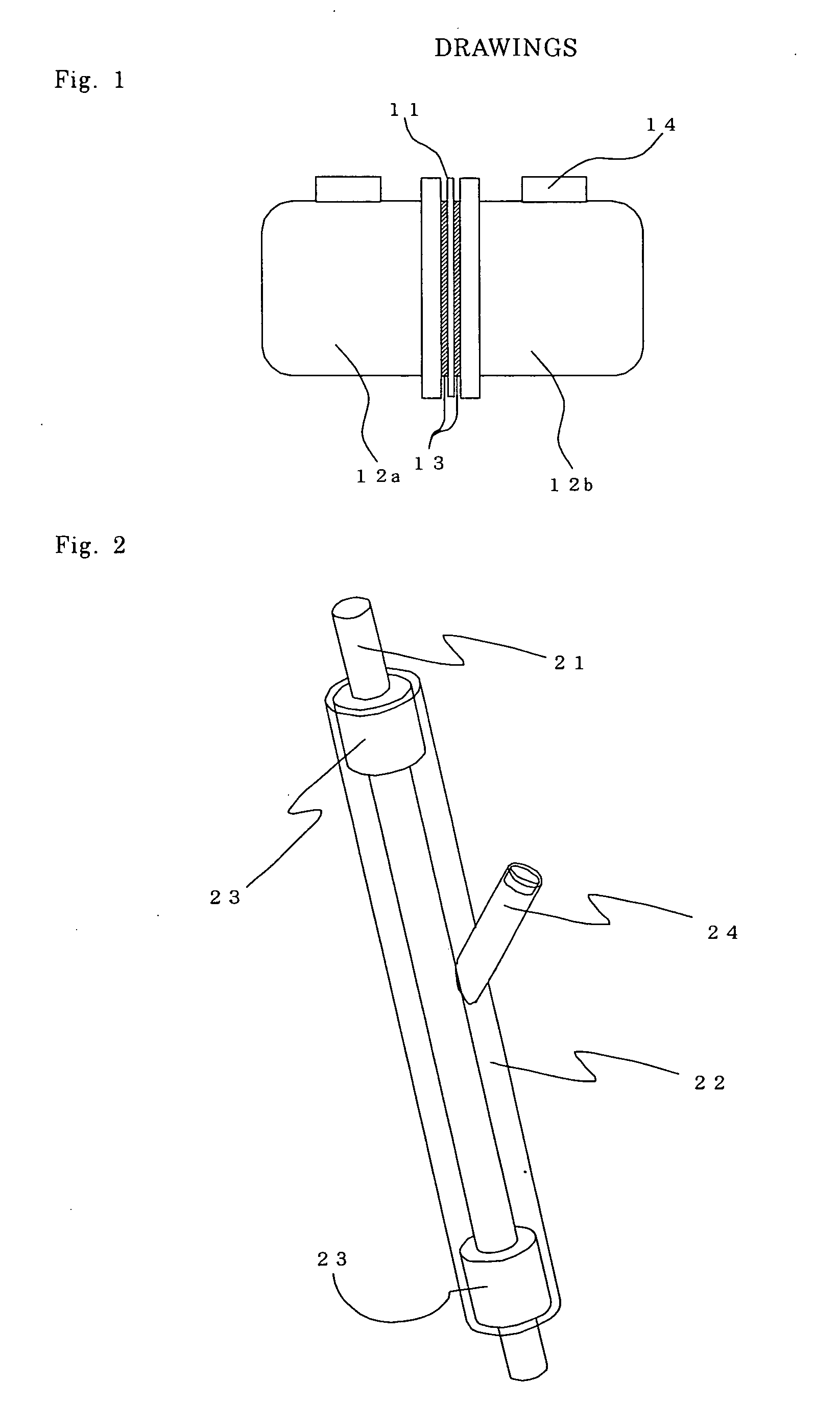

Image

  • Fluid transfer member
  • Fluid transfer member
  • Fluid transfer member

Examples


example 1

[0148] A jacketed mixing vessel-type polymerizer with a capacity of 400 kg of water was charged with 100 kg of demineralized pure water, and the inside space was sufficiently purged with pure nitrogen gas and then the nitrogen gas was eliminated by evacuation. Then, 200 kg of octafluorocyclobutane, 9.13 kg of chlorotrifluoroethylene [CTFE], 20 kg of tetrafluoroethylene [TFE] and 10 kg of perfluoro(propyl vinyl ether) [PPVE] were fed under pressure to the polymerizer, the temperature was adjusted to 35° C. and stirring was started. Thereto was added 0.5 kg of a 50% (by mass) methanolic solution of di-n-propyl peroxydicarbonate [NPP] to initiate the polymerization. During polymerization, the vessel inside pressure was maintained at 0.68 MPa while additionally feeding a monomer mixture prepared so that the composition thereof might be equal to the desired copolymer composition and, after carrying out the polymerization until arrival of the total additional charge amount at about 10% by...

example 2

[0168] The polymerization and after-treatment were carried out in the same manner as in Example 1 except that 19.3 kg of CTFE and 13 kg of TFE were used in the initial monomer charge, to give 20.6 kg of a CTFE copolymer (B) as a granular powder. Since the CTFE copolymer B obtained had a relatively low melting point, the tetrafluoroethylene / perfluoro(methyl vinyl ether) copolymer [MFA] described later in Comparative Example 4, which had a melting point lower than that of PFA, was used as the inner layer of the laminated tube. The copolymer was measured for adhesion strength with PTFE, without carrying out the adhesion strength measurement with PFA or with FEP. Otherwise, the same physical characteristics evaluations as in Example 1 were carried out. The results are shown in Table 2.

[Copolymer-to-PTFE Adhesion Strength Measurement]

[0169] The CTFE copolymer was compression-molded at a temperature higher by 50 to 70° C. than the melting point thereof and at a molding pressure of 5 MPa...

example 3

[0170] The polymerization and after-treatment were carried out in the same manner as in Example 1 except that 5.8 kg of CTFE and 49.6 kg of TFE were used in the initial monomer charge, to give 24.6 kg of a CTFE copolymer (C) as a granular powder. The CTFE copolymer C obtained was evaluated for the same physical characteristics as in Example 1. The results are shown in Table 2.


PUM

PropertyMeasurementUnit
temperatureaaaaaaaaaa
thicknessaaaaaaaaaa

Abstract

The present invention provides a fluid transfer member having thermal stability on the occasion of molding, stress cracking resistance and low liquid chemical permeability at the same time. The present invention is a fluid transfer member which is composed by a laminate containing a layer [P] comprising a fluoropolymer and / or a fluorine-free organic material and a layer [Q] comprising a chlorotrifluoroethylene copolymer.

Description

TECHNICAL FIELD [0001] The present invention relates to a fluid transfer member. BACKGROUND ART [0002] Tubes and like moldings made of a tetrafluoroethylene / perfluoro(alkyl vinyl ether) copolymer [PFA] are resistant to liquid chemicals and hardly contaminate liquids and the like flowing therethrough and, therefore, have so far been used as materials for the piping / tubing system for transferring high-purity liquids, in particular as materials for the piping / tubing system in semiconductor manufacturing equipment, among others. However, PFA tubes have a problem, namely they are fairly high in liquid chemical permeability. [0003] As an outer tube material to be molded in close contact with existing PFA tubes for attaining reductions in liquid chemical permeability, there is described, for example, a polychlorotrifluoroethylene [PCTFE] (cf. e.g. Patent Document 1: Japanese Kokai (Laid-open) Publication H09-137900). However, these tubes still have a problem; namely, when PFA and PCTFE are...

Claims


Application Information

Patent Timeline
Patent Type & Authority Applications(United States)
IPC IPC(8): B32B1/08B32B27/00B32B27/08B32B27/30F16L9/12F16L9/14F16L11/04
CPCB32B27/08F16L9/12Y10T428/1352F16L2011/047Y10T428/1393F16L11/04Y10T428/31536Y10T428/3154Y10T428/31544B32B1/08B32B27/32B32B27/34B32B27/36B32B27/40B32B2323/10
Inventor SHIMONO, TAKESHIAOYAMA, TAKAHISATORIMAE, HIROSHIKITAHARA, TAKAHIRO
Owner DAIKIN IND LTD
Why Eureka
Try Eureka