Tri modal spectroscopic imaging

a spectroscopic imaging and tri-modal technology, applied in the field of tri-modal spectroscopic imaging, can solve the problem of making localized diagnosis more difficult, and achieve the effect of improving sensitivity and specificity of cancer diagnosis and speeding up speed

Inactive Publication Date: 2007-07-19
MASSACHUSETTS INST OF TECH
View PDF28 Cites 22 Cited by
  • Summary
  • Abstract
  • Description
  • Claims
  • Application Information

AI Technical Summary

Benefits of technology

[0011] Ex-vivo tissue measurements performed with LSS imaging system and measurements conducted using tri-modal spectroscopy implemented in a single point instrument showed LSS imaging and TMS can be used for precancer diagnosis. Implementing TMS into an imaging system provides the advantage for screening larger regions of the body at faster speeds. The TMS imaging instrument can improve the sensitivity and specificity of cancer diagnosis with wide-area imaging systems while maintaining their abilities to provide real-time, non-invasive diagnosis.

Problems solved by technology

Note that propagation of diffusely scattered light renders localized diagnosis more difficult because reflectance detected in one area of the tissue may carry contributions from other areas.
Another challenge is to isolate single backscattering, diffuse reflectance, and intrinsic fluorescence so each component can be analyzed separately.

Method used


Image

  • Tri modal spectroscopic imaging
  • Tri modal spectroscopic imaging
  • Tri modal spectroscopic imaging

Examples


Embodiment Construction

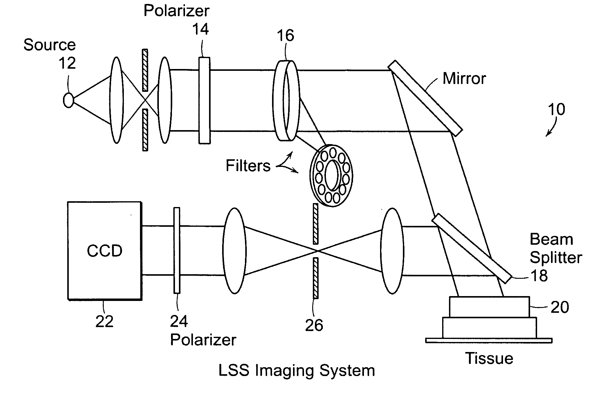
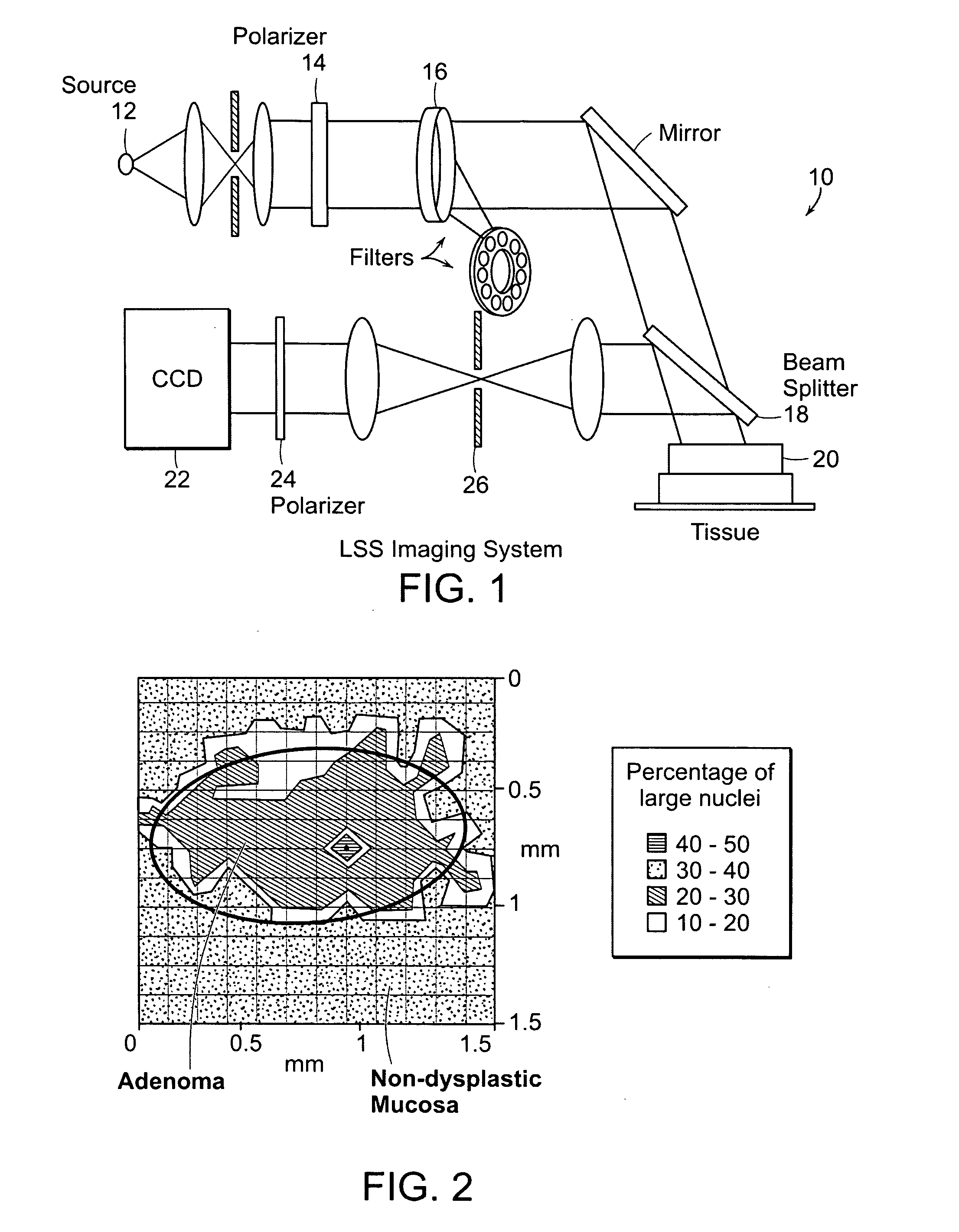
[0030] A spectroscopic imaging system in accordance with a preferred embodiment of the invention can be for precancer detection over a relatively large 1.3 cm by 1.3 cm area, for example. FIG. 1 depicts such a system 10. A 75 W xenon arc lamp light source 12 (Oriel, Inc.) illuminates the tissue 20. The light is collimated with half angle 0.5°, polarized 14, and transmitted through one of 11 narrow-band (4 nm) filters 16 (Edmund Scientific) to select the wavelength in the range 450-700 nm. The reflectance from the tissue is diverted by the beamsplitter 18 to a 4f imaging system 22 that images the illuminated surface of the sample 1:1 onto the CCD (Princeton Instruments, Inc.). The CCD consists of 512×512 pixel array with pixel size 25×25 microns. A polarizer 24 along the collection path selects the polarization state of the collected light. An iris 26 positioned at the center of the 4f lens system collects only light scattered into a solid angle corresponding to a half angle of 0.5°....


PUM


Abstract

The present invention relates to a spectroscopic imaging system using autofluorescence and reflectance images to diagnose tissue. A preferred embodiment of the invention uses a plurality of light sources to illuminate a tissue region to provide the fluorescence and reflectance images, respectively.

Description

CROSS REFERENCE TO RELATED APPLICATION [0001] This application claims the priority of U.S. Provisional Application No. 60 / 702,246, filed Jul. 25, 2005 entitled, TRI MODAL SPECTROSCOPIC IMAGING. The entire content of the above application is being incorporated herein by reference.BACKGROUND OF THE INVENTION [0002] Cancer is the second leading cause of death in the world. Each year, cancer kills over 500 thousand people in the United States alone (National Cancer Institute). Current cancer diagnosis methods usually involve two medical procedures. The first procedure is a wide-area surveillance over the tissue, for example: mammogram, colposcopy, palpation, or visual examination. When warning signs are present, biopsy is performed on the suspicious tissue sites. However, many forms of precancerous and early cancerous lesions are difficult to detect using these traditional surveillance procedures. Therefore, there is a need for wide-area surveillance systems capable of precancer detecti...

Claims


Application Information

Patent Timeline
Patent Type & Authority Applications(United States)
IPC IPC(8): A61B6/00
CPCA61B5/0059A61B5/0066G01J3/02G01J3/0224G01N2021/4733G01J3/10G01J3/32G01N21/4738G01N21/49G01J3/0229
Inventor YU, CHUNG-CHIEHLAU, CONDONFULGHUM, STEPHENFANG-YEN, CHRISTOPHERDASARI, RAMACHANDRAFELD, MICHAEL
Owner MASSACHUSETTS INST OF TECH
Why Eureka
Try Eureka