

Fluorocarbon electrode modification layer
- Summary
- Abstract
- Description
- Claims
- Application Information
AI Technical Summary
Benefits of technology
Problems solved by technology
Method used
Image

Examples
example 4 (
Inventive)
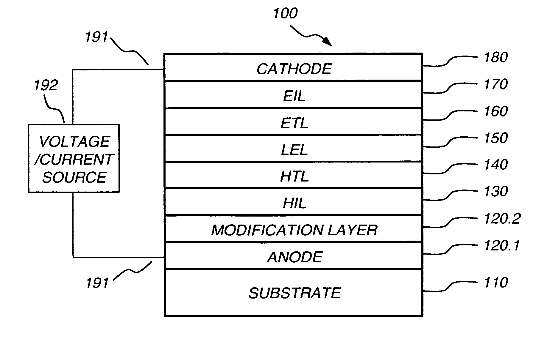
[0172] An OLED, in accordance with the present invention, was constructed as the same as that in Example 1, except that a layer of C60F36, 2 nm thick, was deposited on the oxidative plasma treated ITO surface by thermal evaporation followed by the deposition of the HTL in the same evaporation chamber. The device is denoted as: ITO / O2 / 2 nm C60F36 / 75 nm NPB / 20 nm Alq / 40 nm Alq / 210 nm Mg:Ag.
[0173] This OLED requires a drive voltage of about 6.3 V to pass 20 mA / cm2. Under this test condition, the device has a luminance of about 477 cd / m2, and a luminous efficiency of about 2.4 cd / A. Its color coordinates are CIEx=0.326 and CIEy=0.547, and its emission peak is at 526 nm. Its T50(RT; 80 mA / cm2) is about 790 hours. The voltage rise within the operational lifetime (ΔV) is about 2.0 V. The EL performance data are summarized in Table 1, its normalized luminance vs. operational time, is shown in FIG. 6, and its drive voltage vs. operational time, tested at RT and at 80 mA / cm2, is sh...
PUM
| Property | Measurement | Unit |
|---|---|---|
| Thickness | aaaaa | aaaaa |
| Thickness | aaaaa | aaaaa |
| Thickness | aaaaa | aaaaa |
Abstract
Description
Claims
Application Information