
Polarized plate

a technology of polarized plates and optical films, applied in the field of polarized plates, can solve the problems of film deformation or stress, and film made from the above-mentioned techniques, and achieve the effect of enhancing the mechanical characteristics of the optical film

Inactive Publication Date: 2007-07-26
OPTIMAX TECHNOLOGY CORPORATION
View PDF6 Cites 5 Cited by
  • Summary
  • Abstract
  • Description
  • Claims
  • Application Information

AI Technical Summary

Benefits of technology

[0008]The primary object of the present invention is to provide a polarized plate that contains PMMA and is formed through a solvent-casting process of film. The PMMA is solvable in a non-toxic solvent such as methylbenzene. Hence there is no need to consume a great amount of methane dichloride in the manufacturing process of TAC. As a result, it is less harmful to human body and the environment.
[0009]It is another object of the invention is to provide a polarized plate that has desirable water absorption and moisture permeable properties to eliminate degradation of optical characteristics that might otherwise occur to the polarized plate.
[0010]It is a further object of the invention to provide a polarized plate that is heat-resistant, and has desirable mechanical characteristics and a lower photoelastic coefficient and desirable optical characteristics, such as a lower haze, a smaller yellowness index, and a higher Abbe's number. It has a higher penetrability (>90%) in the range of visible light (wavelength between 400-700 nm) and uniform film surface characteristics (such as thickness, surface coarseness, and the like), and can prevent the unstable material condition caused by melting-mixed processing or thermoplastic fabrication.
[0011]The polarized plate of the invention made from mixed PMMA through solvent-casting process of film has many benefits, including 1. improved heat-resistance, desirable mechanical characteristics, lower photoelastic coefficient and desirable optical characteristics such as a higher transparency, a lower haze, a smaller yellowness index, and a higher Abbe's number, and a higher penetrability (>90%) in the range of visible light (wavelength between 400-700 nm and uniform film surface characteristics (such as thickness, surface coarseness, and the like); 2. prevent unstable material condition caused by melting-mixed processing or thermoplastic fabrication; 3. a desirable moisture permeability and water absorption capability to eliminate degradation of optical characteristics of the optical film; 4. a simpler manufacturing process; 5. a lower photoelastic coefficient; 6. abundant material supply (resin) at a lower cost; and 7. reduce PVA internal shrinkage at high temperature and humidity.
[0016]Furthermore, PMMA and / or PMMA with substituted functional group and / or PMMA elastic rubber particles formed by mixing PMMA with an elastic rubber material may be added to the optical film of the invention. The elastic rubber material may be selected from butyl-acrylate, methyl methacrylate, styrene and polymers thereof. The elastic rubber particles are formed at a size smaller than 10 um or even at a nanometer dimension to enhance the mechanical characteristics of the optical film.

Problems solved by technology

All the TAC films made from the techniques mentioned above have a common drawback, namely they absorb water and have a great moisture permeability.
When used in a high temperature and high humidity condition, the film tends to deform or generate stress due to external environment, and the optical characteristics of the optical film are affected.
In serious cases, the optical film could even become useless.
Moreover, the b-value of TAC is too high.
It is visible from the appearance, and tends to hinder visibility.
In addition, COP film (such as Zeonor, Arton and the like) has too small of water absorption and moisture permeability.
As a result, its adherence capability suffers, and it becomes too brittle.
But the glass transformation temperature of the PET being used is too low (75° C.
), and cannot withstand the temperature required by the optical film now being used.
It is not desirable for the optical film.

Method used


Image

  • Polarized plate
  • Polarized plate
  • Polarized plate

Examples


Embodiment Construction

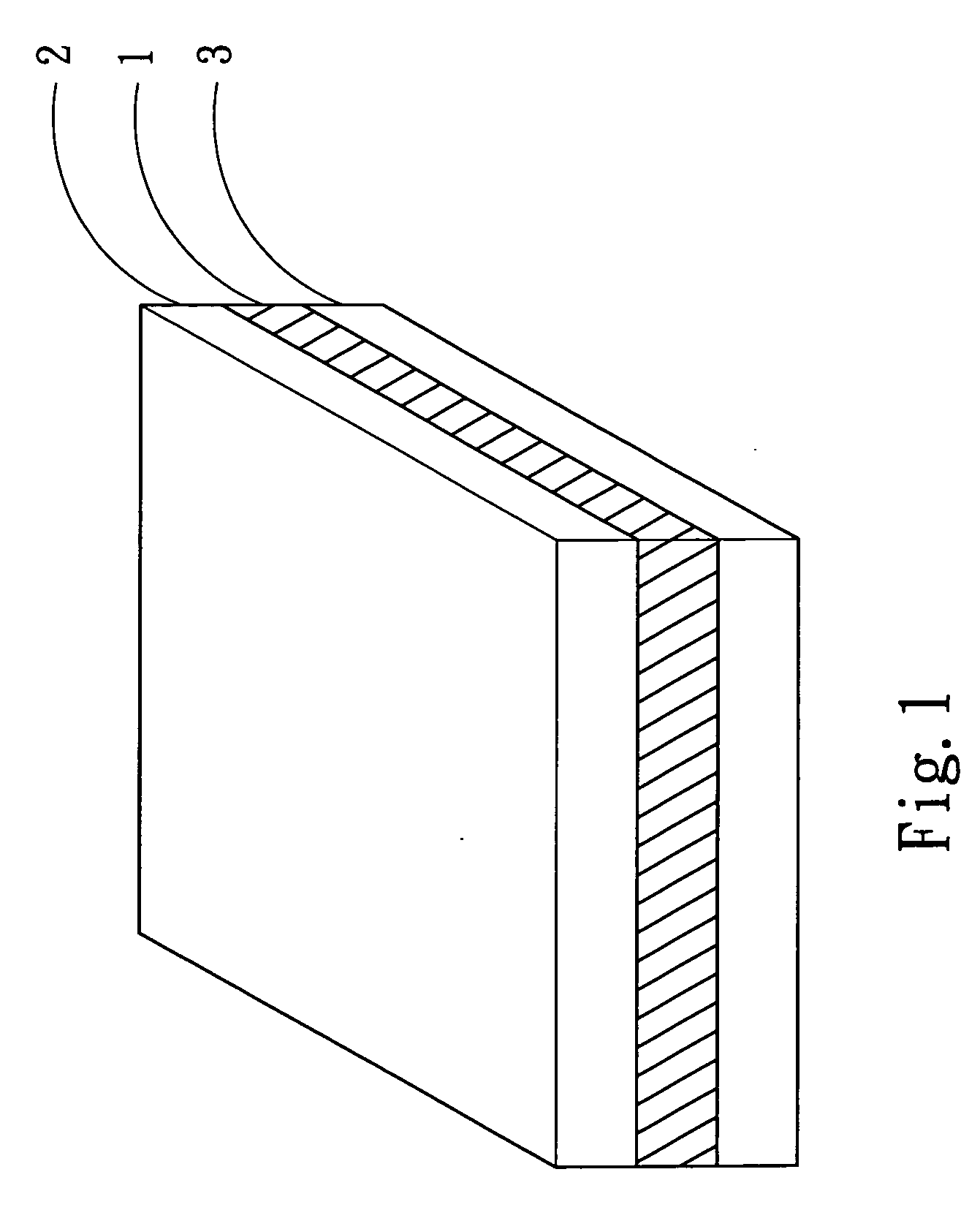
[0022]Refer to FIG. 1 for an embodiment of the invention. The polarized plate of the invention mainly includes a polarized layer 1, a first optical film 2 located on a upper surface of the polarized layer 1 and a second optical film 3 located on a lower surface of the polarized layer 1. At least one of the upper optical film 2 and the lower optical film 3 is made from PMMA.

[0023]Aside from PMMA to make one of the first and second optical films 2 and 3, another optical film may be made from triacetate (TAC), polycarbonate (PC) or cycloolefin polymer (COP) to brace or protect the polarized layer 1.

[0024]The PMMA to fabricate the optical film includes PMMA, PMMA with a substituted functional group, or a mixture of a plurality of PMMAs.

[0025]The TAC in this invention mainly is selected from KC8U made by Konica Co. and TDY-80 made by Fuji CO.

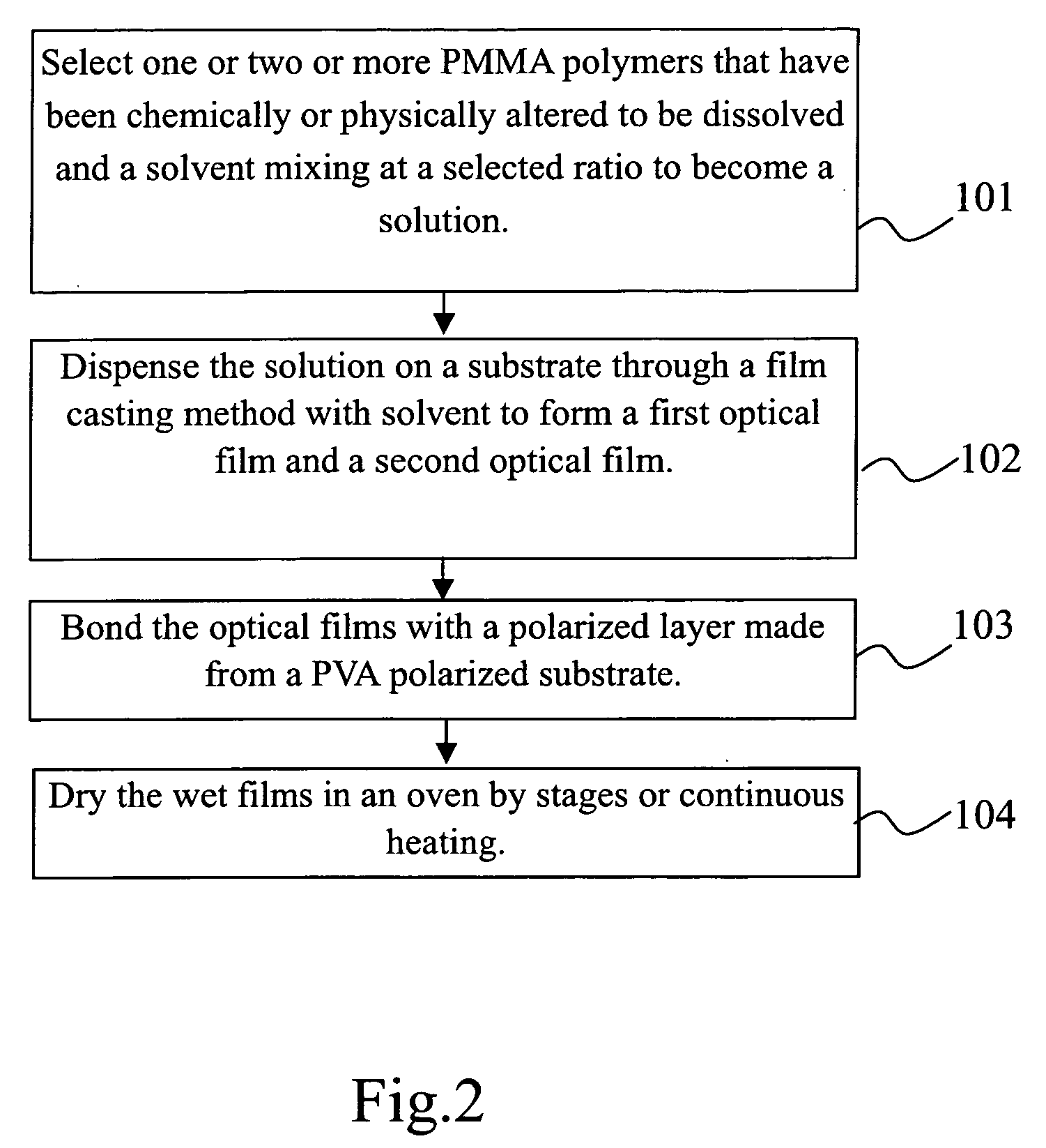
[0026]Refer to FIG. 2 for a manufacturing flow chart for an embodiment of the polarized plate of the invention. First, at step 101, select a PMMA po...


PUM

PropertyMeasurementUnit
Fractionaaaaaaaaaa
Fractionaaaaaaaaaa
Fractionaaaaaaaaaa

Abstract

A polarized plate includes a polarized layer, a first optical film located on a upper side of the polarized layer and a second optical film located on a lower side of the polarized layer. At least one of the first and second optical films is made from Polymethyl Methacrylate (PMMA). The optical films are formed by dispensing a mixed solution on a substrate, then bonding to the polarized layer and processed through a heat treatment. The optical films may also be formed by dispensing the mixed solution on the surface of the polarized layer and processed through a heat treatment.

Description

BACKGROUND OF THE INVENTION[0001]1. Field of the Invention[0002]The present invention relates to a method for manufacturing an optical film by mixing with optical polymers and particularly to a method for manufacturing a Polymethyl Methacrylate (PMMA) optical film through a solvent-casting process of film.[0003]2. Description of the Prior Art[0004]A conventional polarized plate usually consists of a polarized substrate and an optical film located respectively on a upper surface and a lower surface thereof. The optical film mainly is made from triacetate (TAC), polycarbonate (PC), cycloolefin polymer (COP) or the like. A typical TAC film further provides the functions of protecting and bracing the optical film. Hence the general TAC film, aside from having required optical characteristics, also must have a sufficient strength and withstand high temperature and humidity (reference can be found in patents such as JP4342202, TW499573, JP2000-324055, JP2001-235625, JP2003-195048, EP1-285...

Claims


Application Information

Patent Timeline
IPC IPC(8): B32B27/32
CPCG02B5/305Y10T428/31938
Inventor LEE, KUANG-RONGTZENG, YING-DAWANG, TAN-CHINGLIN, YI-JENCHUANG, YU-HWEY
Owner OPTIMAX TECHNOLOGY CORPORATION
Learn More