
Method, members, system and program for bone correction

a technology for osteotomy and assisting members, applied in the field of osteotomy assisting members, can solve the problems of insufficient correction, many defects in actual surgical operations, and difficulty in accurately simulating three-dimensional correction osteotomy surgical operations, and achieve the effect of accurate and easy correction of deformed bones

Inactive Publication Date: 2007-07-26
MURASE TSUYOSHI
View PDF2 Cites 64 Cited by
  • Summary
  • Abstract
  • Description
  • Claims
  • Application Information

AI Technical Summary

Benefits of technology

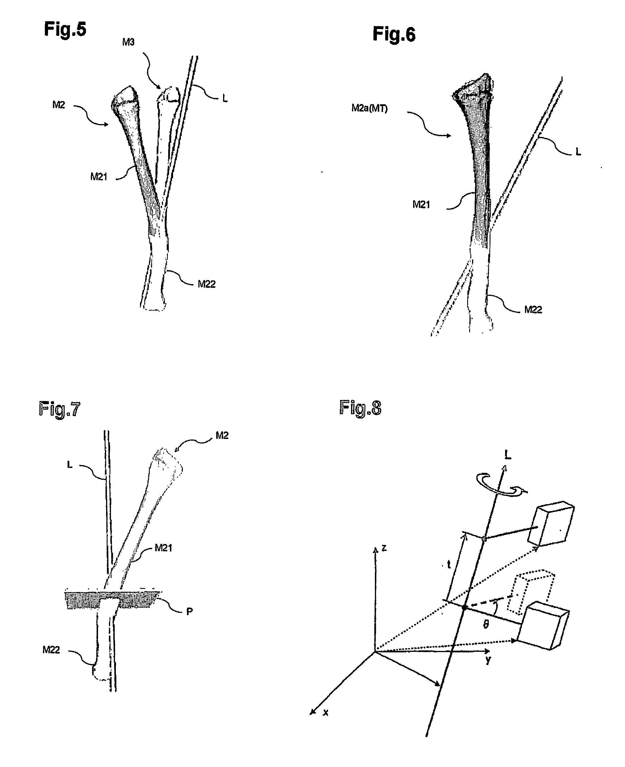
[0006] In more detail, one feature of the present invention is that a difference between a target bone model, representatively showing a shape of a normal bone, and a bone model which is a model of a bone as a subject of treatment (e.g., a malunited bone) is calculated by using the Screw Displacement-Axis method or the affine transformation method, and the difference is compensated for by, for example, rotation, graft insertion, or excision. It has been demonstrated that by performing calculations for rotation, graft insertion, excision or the like directly based on the target bone model and the bone model and executing the treatment according to the present invention, the corrected state of the bone is unexpectedly maintained several weeks or even several months later. Thus, the present invention provides a simple and more accurate method for performing a surgical operation on a body. The present invention provides technology for correcting an abnormal bone such as a deformed bone into a normal shape by cutting the bone substantially once.

Problems solved by technology

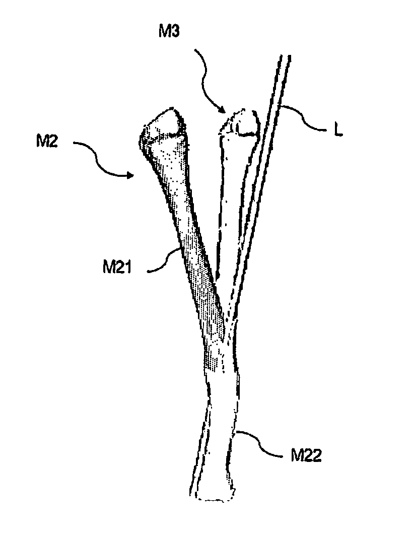
Bone is deformed three-dimensionally, and it is difficult to accurately simulate three-dimensional correction osteotomy surgical operations.
Currently, actual surgical operations have many defects that, for example, the bone is cut at an inappropriate position, and correction is insufficient.

Method used


Image

  • Method, members, system and program for bone correction
  • Method, members, system and program for bone correction
  • Method, members, system and program for bone correction

Examples


example 1

Production of Template Assisting Members and Application Thereof

[0457] In this example, template assisting members were produced after performing a preoperative simulation (FIG. 21) using actual deformed bones as a model. In the case of a fracture malunion on the forearm, the degree of deformity of the radius and the ulna is one of the main factors of restriction of pronation and supination. Pronation refers to rotating the forearm such that the palm is directed downward, and the supination refers to rotating the forearm such that the palm is directed upward (such that the palm is to receive something). It is desirable to correct the deformity as accurately as possible. The present inventor performed accurate correction osteotomy through a preoperative simulation using CR or MRI three-dimensional images. The methods and results will be described below.

[0458] There were 6 cases, and the patients were all male in the age range of 12 to 31 years with the average age of 19.2 years. Th...

example 2

8-Year-Old Male Child; Closed Wedge Osteotomy for Supracondylar Fracture of the Humerus

[0464] In this example, it will be demonstrated that the closed wedge osteotomy is applicable to the present invention. A surgical operation was performed by the method according to the present invention on an 8-year-old male patient having a supracondylar fracture of the humerus, which is a representative fracture around the elbow joint of children. This case is known as easily resulting in cubitus varus. FIG. 27 shows x-rays illustrating the affected site (the left x-ray shows a front view, and the right x-ray shows a side view thereof).

[0465]FIG. 28 shows the progress of hyper-extension in the cast caused by the initial treatment. It is shown that dorsiflexion occurs since no appropriate treatment was performed.

[0466]FIG. 29 shows the state of this patient 2 years after the initial treatment. It is shown that varus deformity and hyper-extension is left and natural correction is not sufficien...

example 3

21-Year-Old Male; Open Wedge Osteotomy for a Left Forearm Fracture Malunion

[0478] In this example, it will be demonstrated that open wedge osteotomy is applicable to the present invention. As an example, a case of a 21-year-old male patient with a left forearm fracture malunion was used. This patient showed an excessive deformity of the radius (FIG. 43). An forearm fracture is often seen among men in early youth to youth, and is considered to often cause a malunion when treated in a cast.

[0479] As shown in FIG. 44, this patient complained of a deformity and restriction of supination of forearm (i.e., such that the palm is to receive something). The supination was restricted to about 40 degrees (normally, 80 to 90 degrees).

[0480] It was found by computer simulation that the deformed bone was matched to the healthy bone by rotating the bone at 30 degrees about the screw axis (FIG. 45). A template was designed based on this information. It was found that by subtracting the bone and ...


PUM


Abstract

The present invention provides a method and a system for treating a bone. The method includes obtaining a bone model representing a bone which is a subject of treatment; obtaining a target bone model to which treatment aims; determining a treatment process (e.g., a necessary assisting member) which is to be performed on the bone based on the bone model and the target bone model; and performing a surgical operation using the determined treatment process. The present invention provides a computer program for performing such a method.

Description

TECHNICAL FIELD [0001] The present invention relates to an osteotomy assisting member and the like preferably used for correcting a bone deformed by fracture or the like into a normal form. BACKGROUND ART [0002] The following description includes information which is considered to be useful for understanding the present invention. The information presented herein is not admitted as prior art for the present invention, or any publications explicitly or implicitly referred to herein is not admitted as prior art for the present invention. [0003] Conventionally, a bone deformity caused by fracture is healed by: first performing preoperative planning using x-rays, CT (computed tomography) images, perspective drawings which are two-dimensional images, and then cutting and correcting bones. Bone is deformed three-dimensionally, and it is difficult to accurately simulate three-dimensional correction osteotomy surgical operations. Currently, actual surgical operations have many defects that,...

Claims


Application Information

Patent Timeline
IPC IPC(8): A61F5/04G06G7/48A61B17/15A61B17/56A61B17/68A61B17/88A61B19/00A61F2/00A61F2/28A61F2/30A61F2/42A61F2/46G16Z99/00
CPCA61B17/15A61B2019/508A61B17/88A61B19/50A61B19/52A61B2017/564A61F2/4261A61F2/4644A61F2002/2835A61F2002/30943A61F2002/30952A61F2002/4649A61F2310/00293G06F19/3437A61B17/8095A61B17/68A61B90/36A61B34/10A61B2034/108G16H50/50G16Z99/00
Inventor MURASE, TSUYOSHI
Owner MURASE TSUYOSHI
Learn More